
- Submit a Protocol
- Receive Our Alerts
- EN

- Protocols

- Articles and Issues
- For Authors
- About
- Become a Reviewer

3D-printed Recoverable Microdrive and Base Plate System for Rodent Electrophysiology

Published: Vol 11, Iss 16, Aug 20, 2021 DOI: 10.21769/BioProtoc.4137 Views: 3614
Reviewed by: Anonymous reviewer(s)
Original research article
The authors used this protocol in:

May 2021

Protocol Collections
Comprehensive collections of detailed, peer-reviewed protocols focusing on specific topics


Abstract
Extracellular recordings in freely moving animals allow the monitoring of brain activity from populations of neurons at single-spike temporal resolution. While state-of-the-art electrophysiological recording devices have been developed in recent years (e.g., µLED and Neuropixels silicon probes), implantation methods for silicon probes in rats and mice have not advanced substantially for a decade. The surgery is complex, takes time to master, and involves handling expensive devices and valuable animal subjects. In addition, chronic silicon neural probes are practically single implant devices due to the current low success rate of probe recovery. To successfully recover silicon probes, improve upon the quality of electrophysiological recording, and make silicon probe recordings more accessible, we have designed a miniature, low cost, and recoverable microdrive system. The addition of a novel 3D-printed skull baseplate makes the surgery less invasive, faster, and simpler for both rats and mice. We provide detailed procedural instructions and print designs, allowing researchers to adapt and flexibly customize our designs to their experimental usage.
Background
High-channel-count and high-density silicon probes can provide unique spatial and temporal information about brain activity (Jun et al., 2017; Steinmetz et al., 2021). Despite the advancement in probe technology, performing extracellular recording is complicated and expensive in freely moving animals using newly developed silicon probes (high-channel-count Neuropixels probe (Jun et al., 2017), light-emitting µLED probe (Wu et al., 2015), or 128-channel active probe (Diagnostic Biochips, Glen Burnie, MD). Effective probe recovery procedures are highly desirable due to the high cost of these devices (Chung J. E. et al., 2017; Juavinett et al., 2019). A 3D printed, recoverable microdrive system for mice (Chung J. et al., 2017; Sariev et al., 2017) and rats (github.com/Mizuseki-Lab/microdrive) allows researchers to reuse silicon probes with ease, decreasing the effective cost of probes. Despite the popularity of head-fixed preparation, there are scientific questions that can be better addressed using freely moving rodents. Therefore, we have designed a microdrive system that can be used for both mice and rats in freely moving experiments (Figure 1). This system allows the user to move the silicon probe inside the brain tissue and fine-tune the position of the recording sites. Although our main goal is to advance the recording device in the brain, other fixed/non-movable approaches are also gaining popularity, especially thosecombined with Neuropixels probes (Juavinett et al., 2019; Luo et al., 2020; Schoonover et al., 2021). Furthermore, to reduce the complexity of the surgery (Vandecasteele et al., 2012), we have designed a hybrid head cap system that consists of a 3D printed plastic base plate with a copper mesh attached to the skull using dental cement. The copper mesh provides structural protection and electrical shielding to the implanted hardware and electronics. The head cap system can be used in a wide range of applications because it is easy to mold the shape of the copper mesh before hardening it with dental cement. Improving the implantation method made our surgeries less invasive and significantly faster, leading to a speedier recovery of the animal. All 3D designs can be printed in the laboratory with a Formlabs Form 2, 3D resin printer, or a 3D printer with similar printing capabilities. We provide detailed procedural instructions and videos allowing researchers to adapt the head cap and recoverable microdrive system. The baseplate was developed for Petersen and Buzsáki (2020) and Vöröslakos et al. (2021), and the microdrives were developed for Vöröslakos et al. (2021)
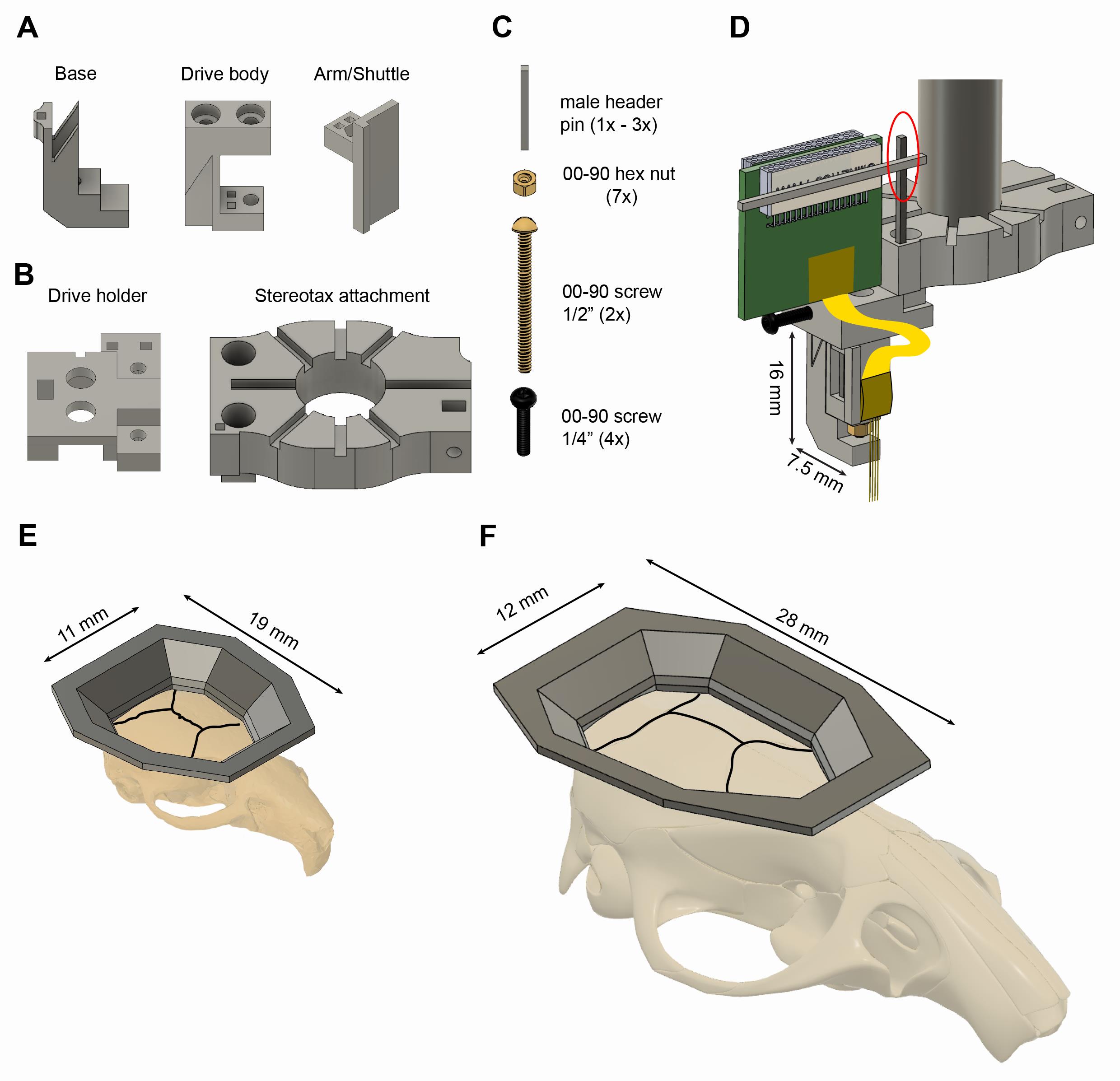
Figure 1. Reusable 3D printed plastic microdrive and base plates for mice and rats. A. The three parts of the 3D printed plastic microdrive: a drive body, a movable arm/shuttle, and a removable base. B. 3D printed stereotaxic attachment and drive holder. All components are 3D printed using resin (Grey-v04, Formlabs Inc.). C. Additional necessary components are 00-90, 1/2” brass screw, a 00-90 brass hex nut, a 00-90, 1/4” stainless steel screw, and header metal bars. D. Stereotaxic attachment with the assembled microdrive and a probe attached, ready for implantation (the red circle indicates the temporary soldering joint for the Omnetics connector). E-F. 3D printed plastic base plate for mice (E) and rats (F) shown on their respective skulls. The black lines represent the sutures of the skull.
Materials and Reagents
Note: All 3D prints were printed and tested in Grey and Clear resins (version-04) using a Formlabs, Form2 3D printer with 50-µm resolution. All design files are available atgithub.com/buzsakilab/3d_print_designs. and specific links are provided below in the material lists.
Microdrive materials
3D-printed microdrive components: body, arm, and base: github.com/buzsakilab/3d_print_designs/tree/master/Microdrives/Plastic_recoverable
00-90 nut (3) (McMaster, catalog number: 92736A112)
00-90 screws, ½” (2) (McMaster, catalog number: 92482A235)
Male header pin (DigiKey, catalog number: SAM1067-40-ND)
00-90 tap (McMaster, catalog number: 2504A14)
Cyanoacrylate (Loctite, catalog number: 45208)
Playdough
1.2 mm drill bit (McMaster, catalog number: 2958A29)
Microdrive holder materials and assembly tools
3D-printed drive holder: github.com/buzsakilab/3d_print_designs/tree/master/Microdrives/Plastic_recoverable (Figure 1B)
00-90 nut (3) (McMaster, catalog number: 92736A112)
00-90 screws, ¼” (1) (McMaster, catalog number: 93701A005)
Male header pin (DigiKey, catalog number: SAM1067-40-ND)
Cyanoacrylate (Loctite, catalog number: 45208)
T2 screwdriver (McMaster, catalog number: 52995A31)
1.2 mm drill bit (McMaster, catalog number: 2958A29)
Stereotax attachment materials and assembly tools
3D-printed stereotax attachment: github.com/buzsakilab/3d_print_designs/tree/master/Microdrives/Plastic_recoverable
00-90 nut (1) (McMaster, catalog number: 92736A112)
00-90 screws, ¼” (3) (McMaster, catalog number: 93701A005)
Male header pin (DigiKey, catalog number: SAM1067-40-ND)
Cyanoacrylate (Loctite, catalog number: 45208)
T2 screwdriver (McMaster, catalog number: 52995A31)
1.2 mm drill bit (McMaster, catalog number: 2958A29)
Hybrid base materials
3D-printed mouse base: github.com/buzsakilab/3d_print_designs/tree/master/Mouse_hat_base
3D-printed rat base: github.com/buzsakilab/3d_print_designs/tree/master/Rat_hat_base
Copper mesh (Dexmet, catalog number: 3CU6-050FA)
Dental acrylic (Pearson Dental, catalog number: G05-1224 and G05-1226)
Surgery materials
Kimwipes (Kimtech, catalog number: 34120)
Gelfoam (Fisher Scientific, catalog number: NC1861013)
H2O2 (Swan, catalog number: S12794v)
C&B Metabond Base 10 ml (Parkell, catalog number: P16-0116)
C&B Gold Catalyst (Parkell, catalog number: P16-0052)
C&B Metabond Clear Powder (Parkell, catalog number: P16-0121)
Ceramic mix dish for metabond (Parkell, catalog number: S387)
Measuring spoons for metabond (Parkell)
Brushes for metabond (Amazon, catalog number: B071F8WSW8)
Unifast Trad Powder Ivory (Pearson Dental, catalog number: G05-1224)
Unifast Trad Liquid (Pearson Dental, catalog number: G05-1226)
UnifastTM 1:2 Package A2 (Pearson Dental, catalog number: G05-0037)
Hair removal cream (Nair)
Povidone-Iodine (Amazon, catalog number: B07MWTH4MW)
Eye ointment (Puralube, catalog number: 0574-4025)
Fountain pen (AmazonBasics, catalog number: FC008A-1-M)
Isoflurane
Bupivacaine
Atropine
Steroids
Buprenex
Cyanoacrylate (Loctite, catalog number: 45208)
Distilled water
Ultrazyme Enzymatic Cleaner Tablets (Ultrazyme, catalog number: B000LM0ZYS)
Equipment
Silicon probes and equipment for attachment to microdrive
Silicon probe (Neuronexus, Cambridge Neurotech, Diagnostic Biochips)
3D printed, assembled microdrive
3D printed, assembled drive holder and stereotax attachment
Helping hand with alligator clip (Ridgerock Tools Inc., catalog number: 01902)
Note: Cover the alligator clip with electrical tape.
Blade (SPI Supplies, catalog number: 05025-MB)
Surgery
Stereotaxic apparatus (Kopf, catalog number: Model 962)
Heating pad (Physitemp, catalog number: TCAT-2LV)
Scalpel handle (Fine Science Tools, catalog number: 10003-12)
Scalpel blade (Fine Science Tools, catalog number: 10015-00)
Fine scissors (Fine Science Tools, catalog number: 14090-09)
Dumont fine forceps (Fine Science Tools, catalog number: 11254-20)
Scraper tool (Fine Science Tools)
Micro Curettes (Fine Science Tools, catalog number: 10080-05)
Dieffenbach Vessel Clips Straight (Harvard Apparatus, catalog number: ST2 72-8815)
Diethrich Mini Bulldog Clamp (Harvard Apparatus, catalog number: ST2 72-8817)
Cotton swabs (Fisher Scientific, catalog number: 19-062-616)
Screwdriver (Amazon, catalog number: B0058ECJIE)
000-120 screw 1/16" (Antrin Miniature Specialties, catalog number: AMS120/1B-25)
Dental drill (NSK, catalog number: Ultimate XL)
Burrs for micro drill 0.7 mm (Fine Science Tools, catalog number: 19008-07)
Soldering iron (Stannol, catalog number: 574104)
Soldering station (Weller, catalog number: WD1)
Solder Flux (Worthington, catalog number: 331928)
Solder Paste (Quick Chip, catalog number: 23271700)
Hair clipper (Wahl, catalog number: 9990-1201)
Dental LED Light (Aphrodite, catalog number: AP-016B)
Ground/reference wire (Phoenix Wire Inc., catalog number: 36744MHW-PTFE)
Procedure
Microdrive assembly (Figure 2A-2M)
Apply a little cyanoacrylate glue (Loctite gel) on the outer surface of a 00-90 brass hex nut, and insert it into the arm.
Push the arm into the opening of the body and align the rectangular holes of the drive body with the rectangular holes of the arm.
Insert male header pins into the drive body through the rectangular holes of the arm.
Critical step: Cut the metal bars to the proper length and make sure they do not extrude from the bottom part of the drive body.
Move down the arm with the male header pins. Apply cyanoacrylate glue on both ends of the male header pins and push back the male header pins into the drive body.
Critical step: Do not apply an excessive amount of superglue on the top of the male header pins as it can flow out and glue the arm to the male header pins. To further prevent this, keep a sufficient gap between the top part of the male header pins and the arm before applying superglue. Wait until the glue is completely cured (15-20 min). If the metal bars extrude at the bottom of the drive, file them and make sure this surface is completely flat and even.
Tap the plastic of the arm component through the brass nut using a 00-90 tap. The diameter of the hole of the arm is 1 mm (right, top part), but the outer diameter of the 00-90 screw is 1.2 mm (right, bottom part).
Insert a 00-90, 1/2” brass screw through the drive body and the arm nut.
Critical step: Make sure the head of the screw is pushed all the way inside the hole on top of the drive body.
Put a 00-90 brass hex nut on the screw.
Critical step: Tighten it completely and then release a quarter-turn (or less). If it is too tight, the arm cannot be moved; if it is too loose, the arm can wiggle and eventually introduce a lot of damage to the brain tissue.
Apply soldering flux and solder to the nut to join the screw and nut together.
Critical step: Try to minimize the amount of time of soldering because an excessive amount of heat will be transferred to the plastic through the metal components. Excessive heat can reduce the structural integrity of the plastic.
Apply superglue on the outer surface on a 00-90 brass nut and insert it into the base component.
Critical step: Make sure that the nut is oriented properly (right side) and inserted all the way. Once inserted, check alignment with the hole (look from the top).
Seal the nut with playdough.
Critical step: Cement needs to be prevented from flowing into this hole during surgery.
Insert assembled drive body into the base.
Insert a 00-90 1/2" brass screw into the drive body and secure the drive body to the base.
Critical step: Hold the base component still using a plier and try to move the arm while looking for any movement of the body relative to the base under a microscope. If the body moves, then 1) the bottom of the drive might not be flat, 2) the back screw might not tightened enough, or 3) the print did not come out with proper dimensions, and there is extra space somewhere between the base and drive body.
The fully assembled microdrive weighs 0.67 g, and its dimensions are 3.2 × 7.5 × 16 mm (width x length × height).
Additional features:
The arm can be customized to any size. We share arm designs on our Github page for 64 and 32-ch silicon probes with 5 mm shank length.
There is a rectangular hole in the back of the base component in which a male header pin can be ‘glued’ using dental cement. This male header pin can serve as a temporary soldering joint during multi-probe implants.
Critical step: Do not use super glue to attach this bar. The advantage of using dental cement is that the male header pin can be removed post-surgery by melting it with a soldering iron. Applying heat to the metal bar can release it from cement but not from superglue. Be careful with heat because an excessive amount of heat can deteriorate the base component.
The drive holder has a hole to accommodate this male header pin during probe recovery, but it makes the alignment more difficult.
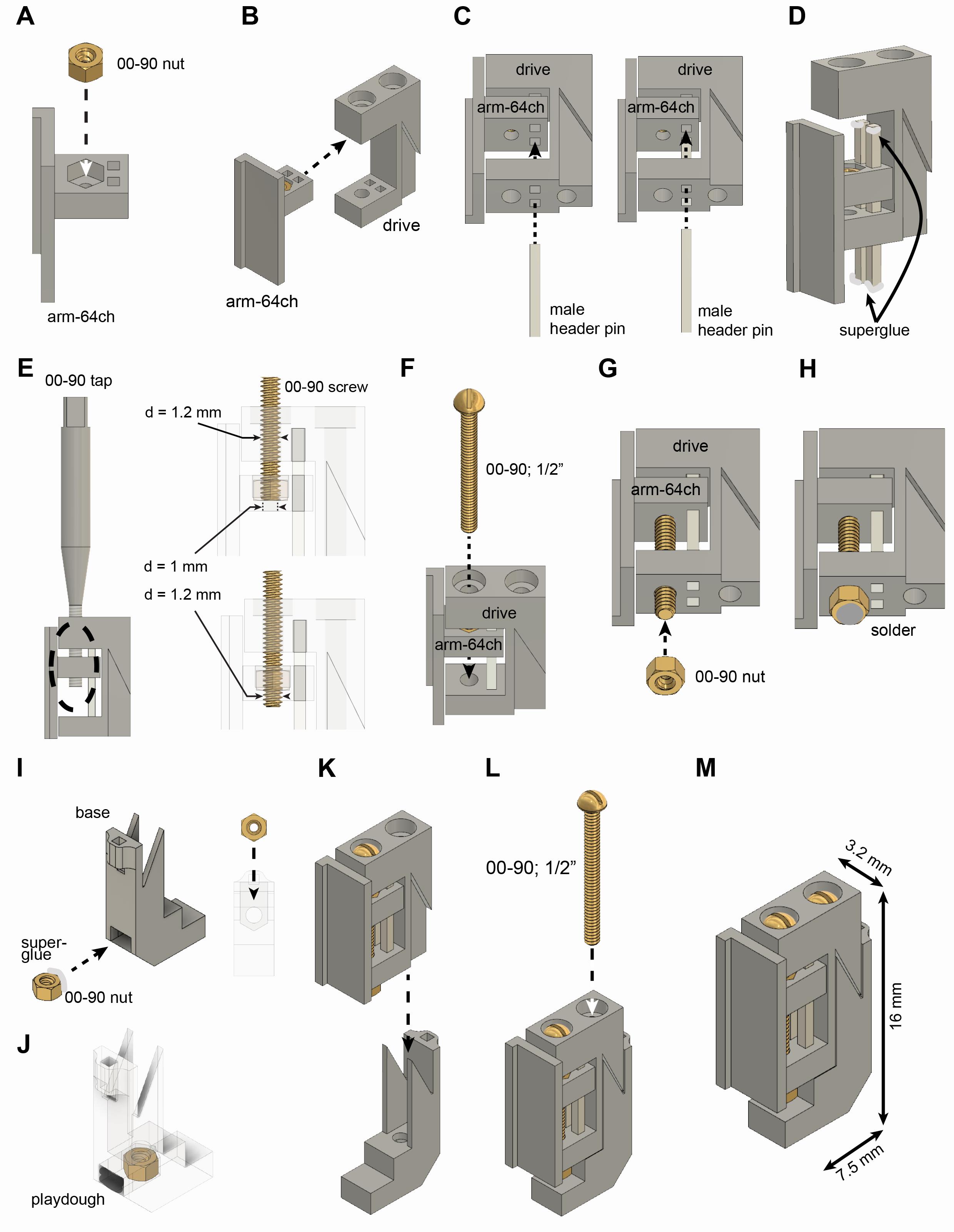
Figure 2. Assembly of recoverable microdrive. See instructions in section A above.
Drive holder and stereotax attachment assembly (Video 1 and Figure 3)
Apply superglue on the outer surface on a 00-90 brass nut and insert it into the stereotax attachment component (Figure 3A).
Critical step: Make sure that the nut is oriented properly (similar orientation to base) and inserted all the way. Once inserted, check alignment with the hole (look from the side).
Apply super glue on one side of a male header pin and insert it into the stereotax attachment component (Figure 3A).
Critical step: Once the glue is cured completely, apply soldering flux and solder to the metal bar (around the height where you expect to solder your omnetics connector).
Insert a 00-90 1/4" stainless steel screw (Figure 3B).
Critical step: When attached to the arm of the stereotax, never tighten this screw too much as it can break the plastic.
Apply superglue on the outer surface of a 00-90 brass nut and insert it into the bottom of the drive holder component (Figure 3C).
Apply superglue on the outer surface of a 00-90 brass nut and insert it into the drive holder component (Figure 3D).
Critical step: Make sure that the nut is oriented properly (similar orientation to base) and inserted all the way. Once inserted, check alignment with the hole (look from the side).
Attach stereotax attachment to drive holder using two 00-90 1/4" stainless steel screws (Figure 3E, step 1).
Insert a 00-90 1/4" stainless steel screw into the drive holder component (Figure 3E, step 2).
Additional features:
There are two rectangular holes on the drive holder component that can be used for male header pins. These pins can serve as a temporary soldering joint for the Omnetics connector of the silicon probe.
The drive holder can be redesigned in multiple ways, e.g., the securing screw can be moved from the side to the front.
 Video 1. How to assemble drive holder, stereotax attachment, and recoverable microdrive
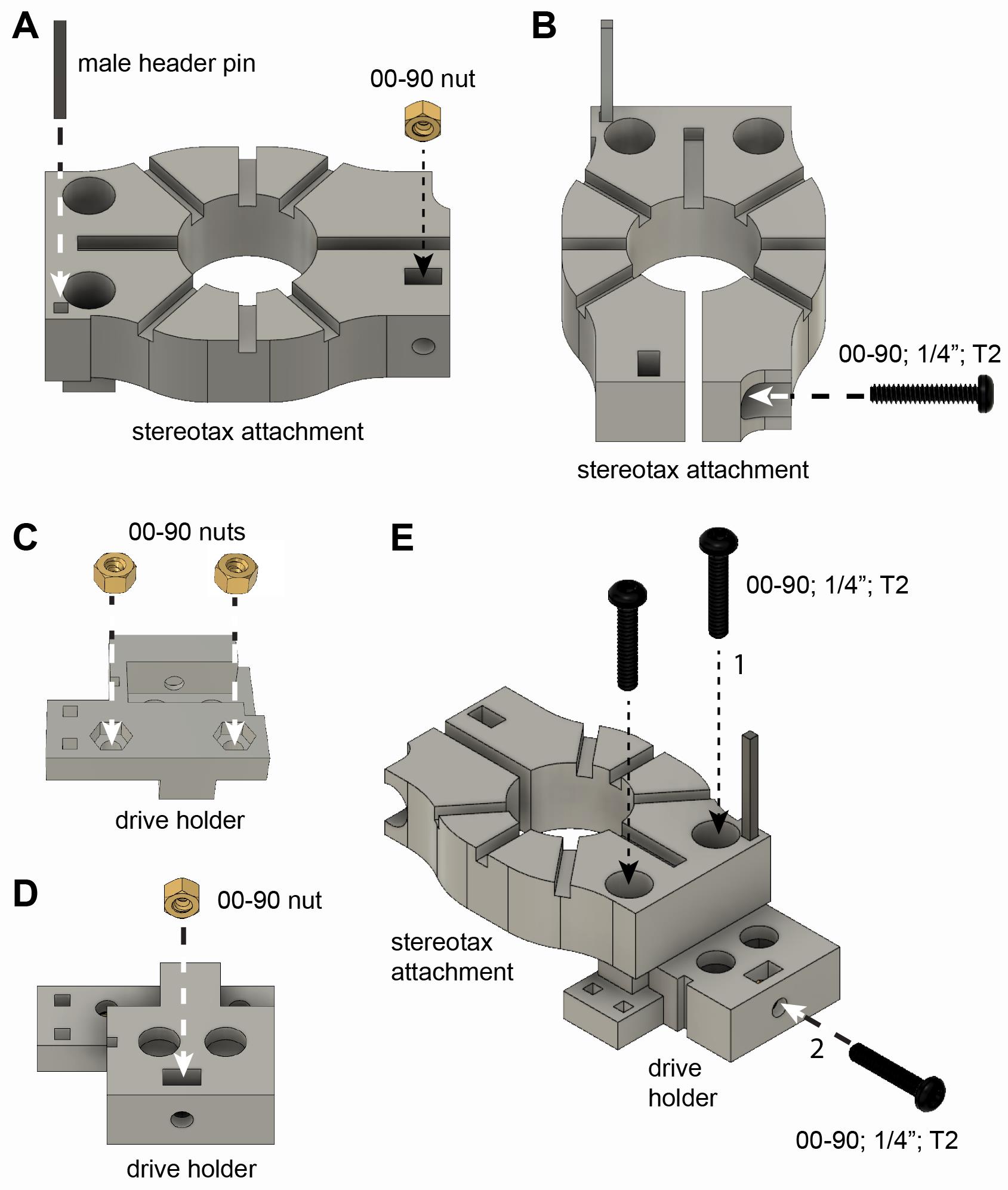
Figure 3. Assembly of stereotax attachment and drive holder. See instructions in section B above.
Attaching the probe to the microdrive (Video 2 and Figure 4)
Scratch the surface of the Omnetics connector using a blade (Figure 4A).
Critical step: It is important to increase the surface of the plastic connector to ensure better adhesion between Omnetics and the male header pin.
Attach male header pin to the Omnetics connector using superglue or dental cement (Figure 4B).
Critical step: Wait until the glue is cured completely.
Cover the male header pin with dental cement (arrow in Figure 4C).
Critical step: Make sure to use relatively liquid cement to let it flow between the metal bar and the Omnetics. Pay attention not to let the cement flow into the Omnetics connector. In general, one male header pin is enough for 32-ch silicon probes, but two should be used for 64-ch probes.
Apply soldering flux and solder to both ends of the male header pin (arrow in Figure 4D).
Critical step: Excessive heat can melt the cement and/or Omnetics. Try to work as fast as possible.
Hold the drive with one helping hand and the probe with another one. Align the probe backend with the arm of the drive (Figure 4E).
Apply superglue or dental cement to the arm (Figure 4F).
Attach the backend of the probe to the arm. Fine-tune the position of the probe using a tweezer (Figure 4G).
Critical step: For 10-15 s, the backend of the probe can be moved, and alignment can be fine-tuned.
Holding the stereotax attachment with the hand, attach the drive holder to the drive and tighten the screw (Figure 4H).
Critical step: Make sure it is tight enough but do not force it because the metal screw can break the plastic drive.
Solder the Omnetics connector to the male header pin (circle in Figure 4I).
Realign the drive inside the drive holder (if necessary). Hold the stereotax attachment with your hand and flip it upside down. Loose the screw of the drive holder and realign the drive (Figure 4J).
Tighten the screw again (Figure 4K).
Critical step: Make sure it is tight enough but do not force it because the metal screw can break the plastic drive.
Make sure there is no tension on the flexible cable of the silicon probe (Figure 4L).
Critical step: If there is tension on the cable, solder the Omnetics to a new position where the tension is released.
Video 2. How to attach a silicon probe to a recoverable microdrive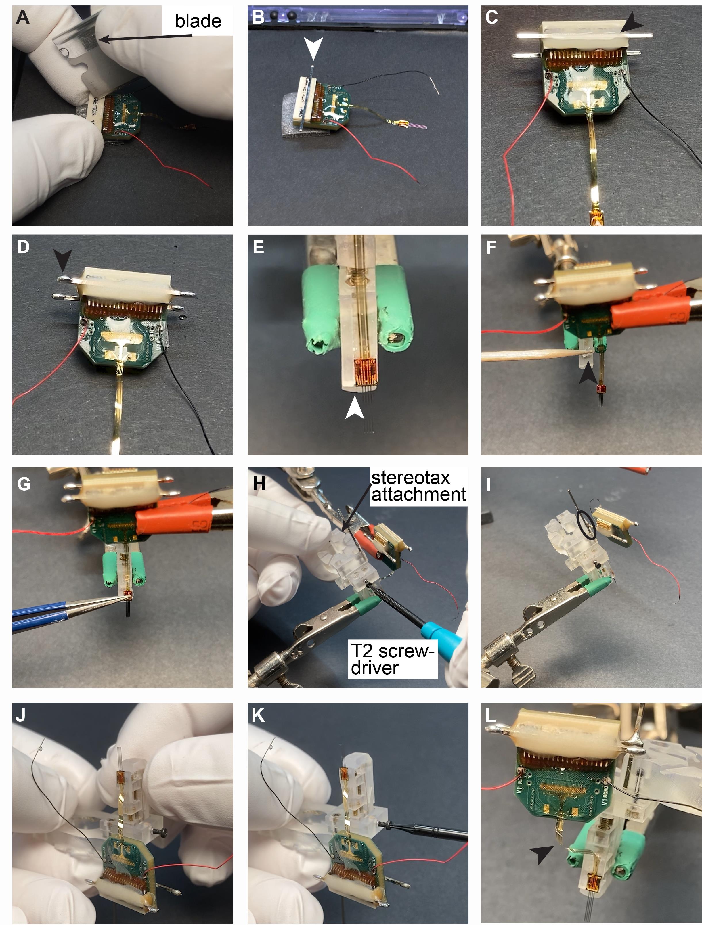
Figure 4. Attaching the silicon probe to the recoverable microdrive. See instructions in section C above.
Attaching copper mesh to mouse base plate (Video 3)
Cut a 7 cm × 7 cm square of copper mesh (Figure 5A).
Mark the interior of the base plate at the center of the copper mesh with a pen and carefully cut out the interior with small scissors (Figure 5B and 5C).
Realign the copper mesh to the base plate and mold the mesh to the shape of the plastic base (Figure 5D).
Critical step: Make sure the copper mesh does not overhang at the bottom.
Attach the copper mesh to the base plate using very liquid dental cement (Figure 5E).
Critical step: The cement must be liquid enough to flow between the holes of the copper mesh to attain a strong bond to the plastic base.
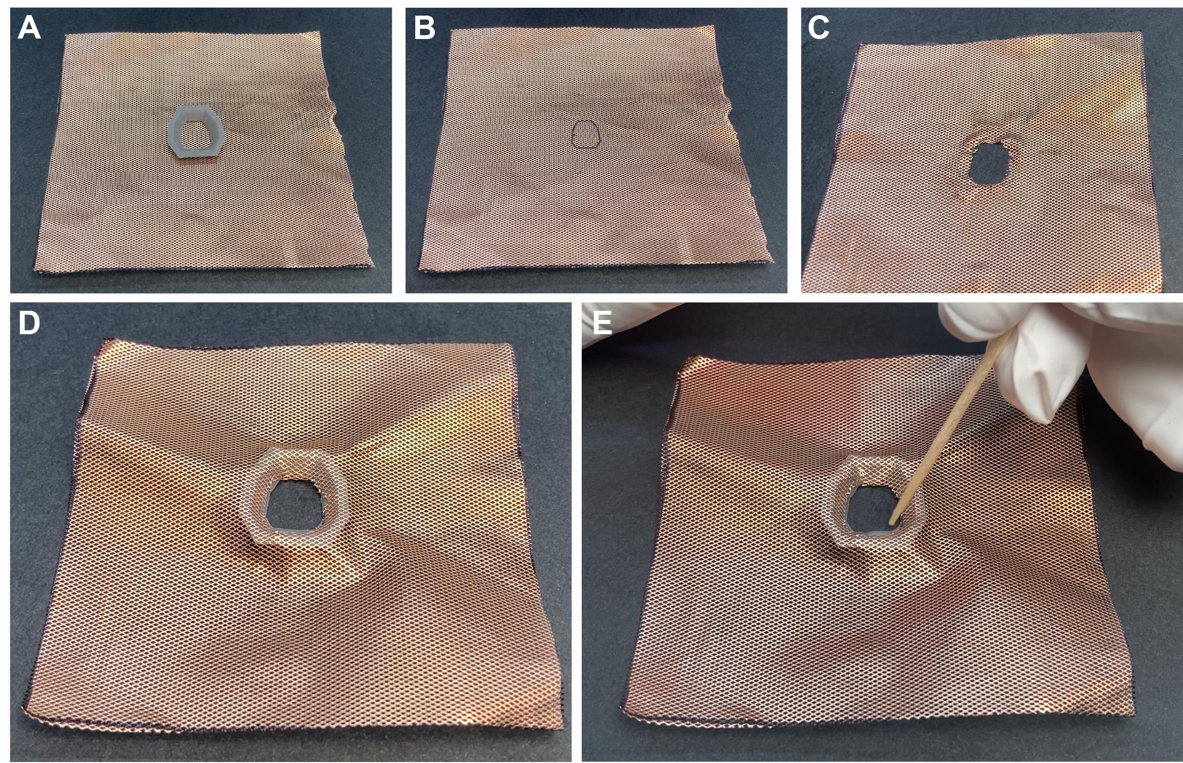
Figure 5. Preparing base plate for mice. A. Copper mesh with the baseplate. B. Cutout of the interior of the base plate. C. Cutout at the center of the copper mesh. D. Realigned copper mesh to the base plate. E. Attachment of the copper mesh to the base plate with dental cement.
Attaching copper mesh to rat base plate (Figure 6)
Cut an 8 cm × 16 cm piece of copper mesh. Fold it in the middle to obtain an 8 × 8 cm double layer of copper mesh (Figure 6A).
Critical step: Apply soldering flux and solder in different points (Figure 6B).
Mark the interior of the base plate on the copper mesh (Figure 6C and 6D).
Cut out the copper mesh.
Attach the copper mesh to the base plate (Figure 6E).
Critical step: Make sure the copper mesh does not overhang at the bottom.
Attach copper mesh to the base plate using very liquid dental cement (Figure 6F).
Critical step: If the cement is not liquid enough, it cannot flow between the holes of the copper mesh, and it cannot attach the copper mesh to the plastic properly.
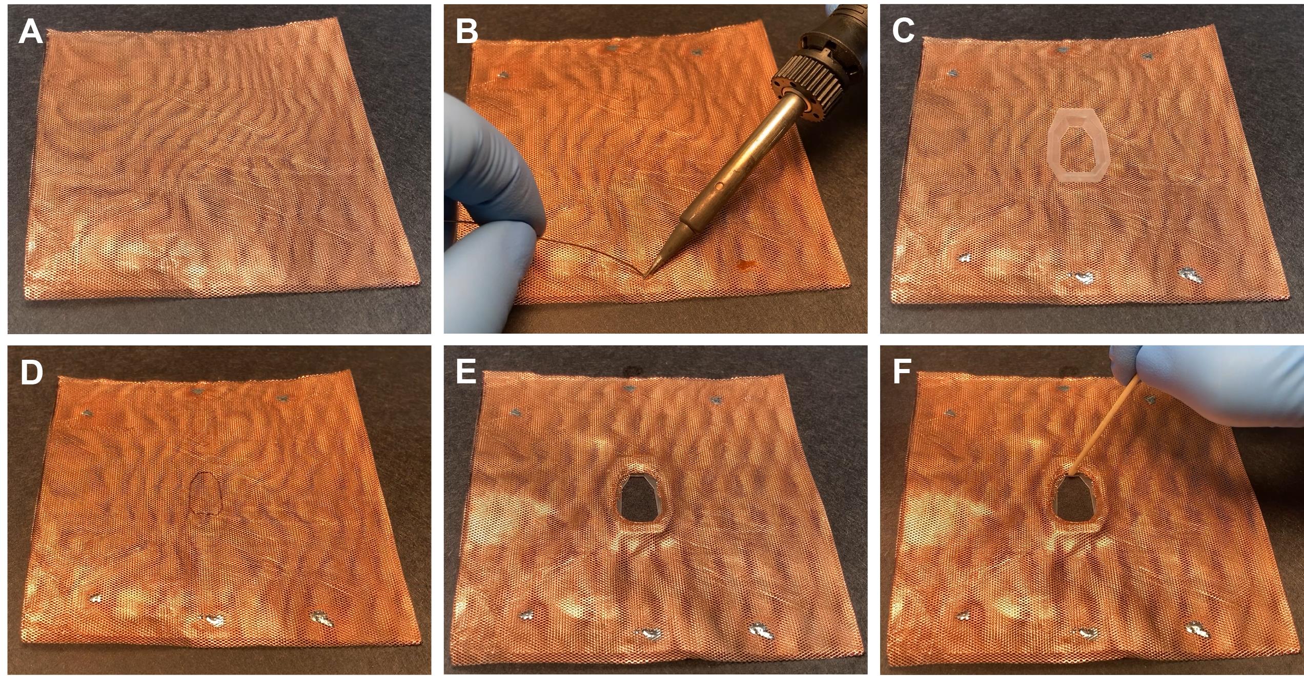
Figure 6. Preparing base plate for rats. A. Copper mesh folded into a square. B. Applying solder to the copper mesh. This will prevent the opening of the folded, double-layer copper mesh during surgery. C. Copper mesh with baseplate. D. Cutout at the center of the copper mesh. E. Realigned copper mesh to the base plate. E. Attachment of the copper mesh to the base plate with dental cement.
Preparing ground and reference wire (Figure 7)
Cut the ground wire to the appropriate length and remove the insulation from both sides (Figure 7A).
Apply solder to the uninsulated part of the wire (Figure 7B).
Cut the end of the wire that will be soldered to the screw very short (it should not be longer than the head of the screw, see Figure 7C).
Hold a 000-120 1/16” pan head screw in a wise or helping hand and apply liquid soldering flux on the head of the screw (Figure 7D, arrow).
Apply a small amount of solder to the head of the screw (Figure 7E).
Critical step: Make sure not to fill up the hole for the screwdriver with solder.
Solder the ground wire to the head of the screw (Figure 7F).
Note: Store the ground wire in alcohol (at least 70%) until surgery.
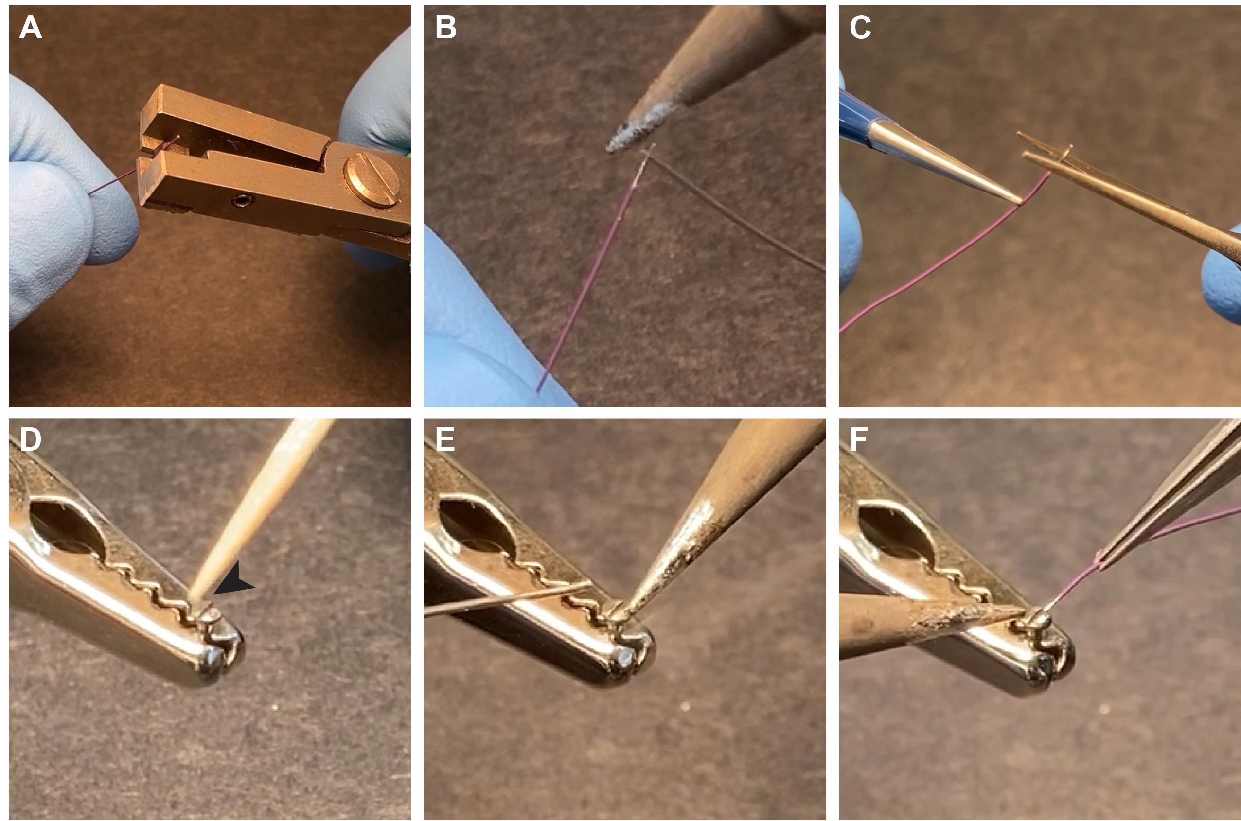
Figure 7. Preparing ground screw. A. Wire isolation is stripped with a wire stripper. B. Solder is applied to the uninsulated part of the wire. C. Cut the stripped wire so that it is the same length as the head of the screw. D-F. Flux paste is applied (D) to the steel ground screw (000-120 1/16" screw), and a drop of solder is attached to the screw (E) before the ground wire is soldered to it (F).
Implanting procedure (Video 3)
Numbered steps are not shown in any of the pictures.
Prepare the stereotaxic apparatus and tools.
Place the heating pad under the position of the ear bars.
Sterilize surgical instruments.
Weigh the animal subject.
Anesthesia and pre-incision preparations.
The animal is anesthetized for 3 min (after it passes out) in an anesthesia-bucket with 2.5:1.5 (Anesthetic % to Airflow ratio).
Fixate animal with ear bars and closed ventilation nosepiece. Once the animal is in the stereotax, the level of anesthesia can be lowered (1.2-2%). Apply a local anesthetic to the tips of the ear bars before inserting them into the ears (LMX-4 Lidocaine 4% topical cream).
Remove the fur on the head of the animal around the surgery incision using either Nair-hair remover or a hair trimmer.
The hairless skin is cleaned with antiseptic solution (Povidone-Iodine – 10% topical solution). The skin is cleaned by three separate antiseptic cleanings, performed with Kimtech wipes by anterior to posterior swipes. The last swipe must be done in one stroke to minimize infections. Between each swipe, the skin is cleaned with 70% alcohol.
Incision and skull cleaning.
Inject bupivacaine (0.4-0.8 ml/kg of a 0.25% solution) as local anesthesia subcutaneously along the scalp midline. Make one injection site and distribute the anesthetics along the midline.
A median incision is made from the position of the eyes to the back of the skull (neck).
The skin is released from the skull, pulled aside, and fixated with four bulldogs. The bulldogs are attached to the second skin layer.
Scrape the skull with a sharp object (forceps or scalpel) to remove any tissue along the top flat surface of the skull. This minimizes electric noise artifacts and affirms a strong bond of the 3D printed base.
Clean the skull with saline and vacuum suction.
Clean the skull with hydrogen peroxide and rinse with saline. The hydrogen peroxide is applied with cotton swabs (about 5 s) and rinsed quickly and thoroughly thereafter with saline.
Cauterize any bleedings along with the skull and exposed skin.
Attaching the base to the skull.
Mix four drops of base with one drop of catalyzer. Paint, using a brush, the whole surface of the cleaned and dried skull and let it dry (Figure 8A). Mix a new solution of Metabond with powder: four drops of base, one drop of catalyzer, and two scoops of powder and paint the skull surface with Metabond. Pay attention to paint along the edge of the skull surface.
Critical step: Prepare the Metabond on ice as it will extend the working time. We recommend using clear powder, which makes it possible to see through it (the sutures and skull landmarks remain visible).
Paint the bottom surface of the 3D printed base with Unifast LC cement (arrow), align it above the skull, and attach it to the skull before it solidifies (Figure 8B).
Critical step: Paint only a small portion of the base at a location far from the region of interest. This step helps to quickly attach the base to the skull.
This step can also be performed with metabond, but the curing takes longer.
Cure the Unifast LC using blue light (10-20 s, Figure 8C).
Paint along the inner contact line between the hat base and the skull with relatively liquid dental cement, creating a sealed area inside the hat (Figure 8D, black arrow – already sealed side, white arrow – not yet sealed).
Critical step: The cement should be liquid enough to be able to flow between the skull and base.
The finished result should look like Figures 12A-12C.
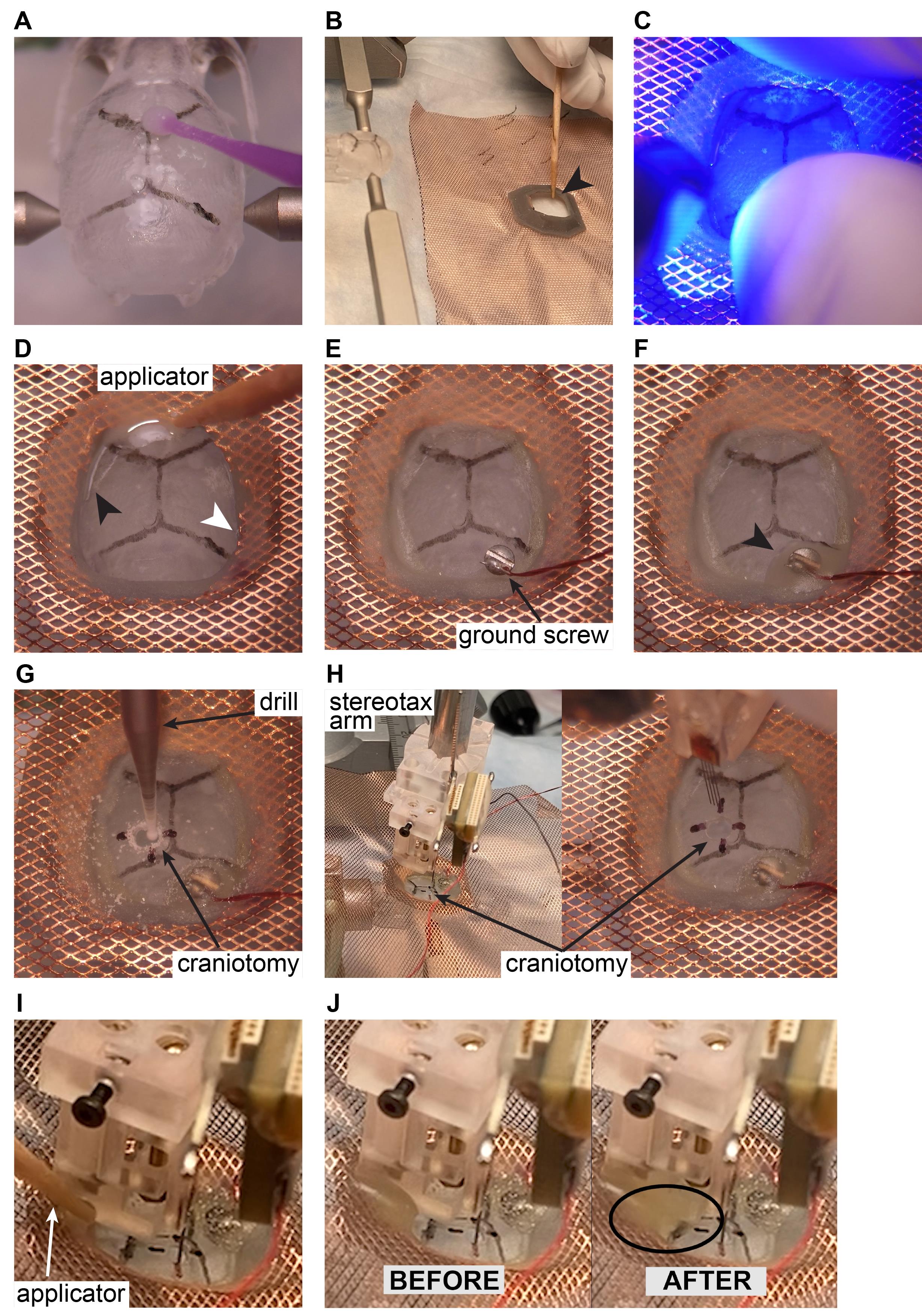
Figure 8. Silicone probe implantation in rodents. The ‘surgery’ is performed on a 3D-printed mouse skull. Note that all these steps are identical for mice and rats.Craniotomy marking and screw placement.
Align Bregma and Lambda in the same horizontal plane. Determine the position of Bregma using stereotactic coordinates with a fine syringe needle attached to the stereotactic arm.
Calculate the relative positions of the probe incision points.
Mark the positions of the craniotomies with scalpel and pen (fill the scalpel-drawn lines with the pen).
Mark the position of the reference and ground screws with the scalpel/pen.
Remove the stereotaxic arm.
Drill holes for the ground screw over the cerebellum with the drill (0.7 mm). If bleeding occurs, rinse with saline and vacuum suction until bleeding stops. Screw the ground screw in (Figure 8E). Begin with a slight counterclockwise turn.
Critical step: For mice, allow a margin of about 0.5 mm (about the height of the forceps). In rats, screw the screws tight. Position the head of the screw in such a way that the ground cable is not in the way (facing outward).
Note: 125 µm steel wires can also be used for reference and ground instead of screws.
Cover and completely seal the ground screw with dental cement (Figure 8F, arrow).
Note: We recommend using Unifast LC cement as it can be fully cured in 20 s.
Craniotomy.
Using a 0.7-mm drill, prepare the craniotomy (Figure 8G). Rinse with saline and vacuum suction to ensure visibility while drilling.
Critical step: Clean around the craniotomy with the drill or the scraping/sharp scooping tool. Remove the dura with a hooked-shaped needle at the incision points of probes: Bend the tip of the 30G needle to form the hook shape to create a better grip-angle to pull the dura without damaging the cortex. You can lift the dura while pulling back with the needle tip and perform the cut with a scalpel. Avoid blood vessels. Apply saline and Gelfoam to the craniotomy to maintain a wet brain surface.
Probe implantation.
Attach the implantation tool with a silicon probe to the stereotax arm and position the silicon probe according to specified surface coordinates (Figure 8H).
Critical step: Drive the silicon probe to the surface of the brain and mark the dorsoventral coordinate. Implant the probe to the desired target depth.
Attach the base of the microdrive to the skull and hat-base with dental cement (Figure 8I).
Critical step: Use relatively liquid dental cement to let it flow between the skull and base component but be careful not to let it flow into the craniotomy. Do not ever touch the microdrive. If the gap is too big, start building up cement from the skull.
Note: We recommend using Unifast LC cement as it can be fully cured in 20 s. As this step can take multiple rounds of application of dental cement, fast curing can save significant time on the overall time of the surgery.
Fill all gaps with dental cement between the base component and the skull surface (Figure 8J).
Apply silicone to the craniotomy, letting the silicone run along the shanks, sealing the craniotomy completely. This protects the brain long term and limits bleedings and coagulation (Figure 9K).
Note: Alternatively, apply paraffin oil/wax to the craniotomies with narrow forceps and heat (using the soldering tip).
Loosen the screw of the drive holder using a T2 screwdriver (Figure 9L).
Detach the probe PCB from the stereotax attachment (Figure 9M, black circle).
Critical step: Lay down the probe PCB on the copper mesh, and make sure there is no tension on the flexible cable.
Move the stereotax arm upwards (Figure 9N, dashed arrow).
Critical step: Monitor shanks while moving upwards with the stereotax. If there is any movement of the shanks, stop immediately and check that everything is properly aligned.
Building a copper mesh cage for mice.
Attach a male header pin (Figure 9O, arrow) to the plastic base/skull. Hold the metal bar with a tweezer until the dental cement is cured with blue light.
Critical step: Bend the metal bar (making an L-shape with 100-120 degrees angle) and apply dental cement to this short, bent part of the metal bar, and attach it to the base. Make sure to cut the metal bar to the proper height before attaching it to the base.
Apply solder to the tip of the metal bar (Figure 9P, arrow).
Critical step: Do not apply an excessive amount of heat (long time of soldering) because the heat transferred by the metal can melt the dental cement causing structural deterioration of the copper mesh cage.
Attach the probe PCB to the male header pin installed in the previous step (Figure 9Q).
Attach three more male header pins in the three remaining corners (Figure 9R, arrows). Apply solder on the tip of all of them.
Attach a male header pin across one side. Repeat with the remaining open sides (Figure 9S).
Critical step: Cut the length of the metal bar to the proper length before soldering it to the cage.
Cut the copper mesh along the diagonals, all the way to the plastic base (Figure 9T).
Fold up the copper mesh and cut it to the appropriate height (Figure 9U, arrow).
Solder the copper mesh to the male header pins (Figure 9V).
Repeat the cutting, folding, and soldering on all sides (Figure 9W).
Attach ground wire from probe PCB and from ground screw to copper mesh using solder (Figure 9X).
Critical step: Arrange the wires inside the cage in a way that does not block access to the screw of the microdrive.
Note: If using separate ground and reference wires, attach them accordingly.
Using the handle of a tweezer (Figure 9Y, circle), smooth out the edges, if necessary. Secure the edges with solder if necessary.
Video 3. Preparation of mouse base plate and implantation of silicon probe
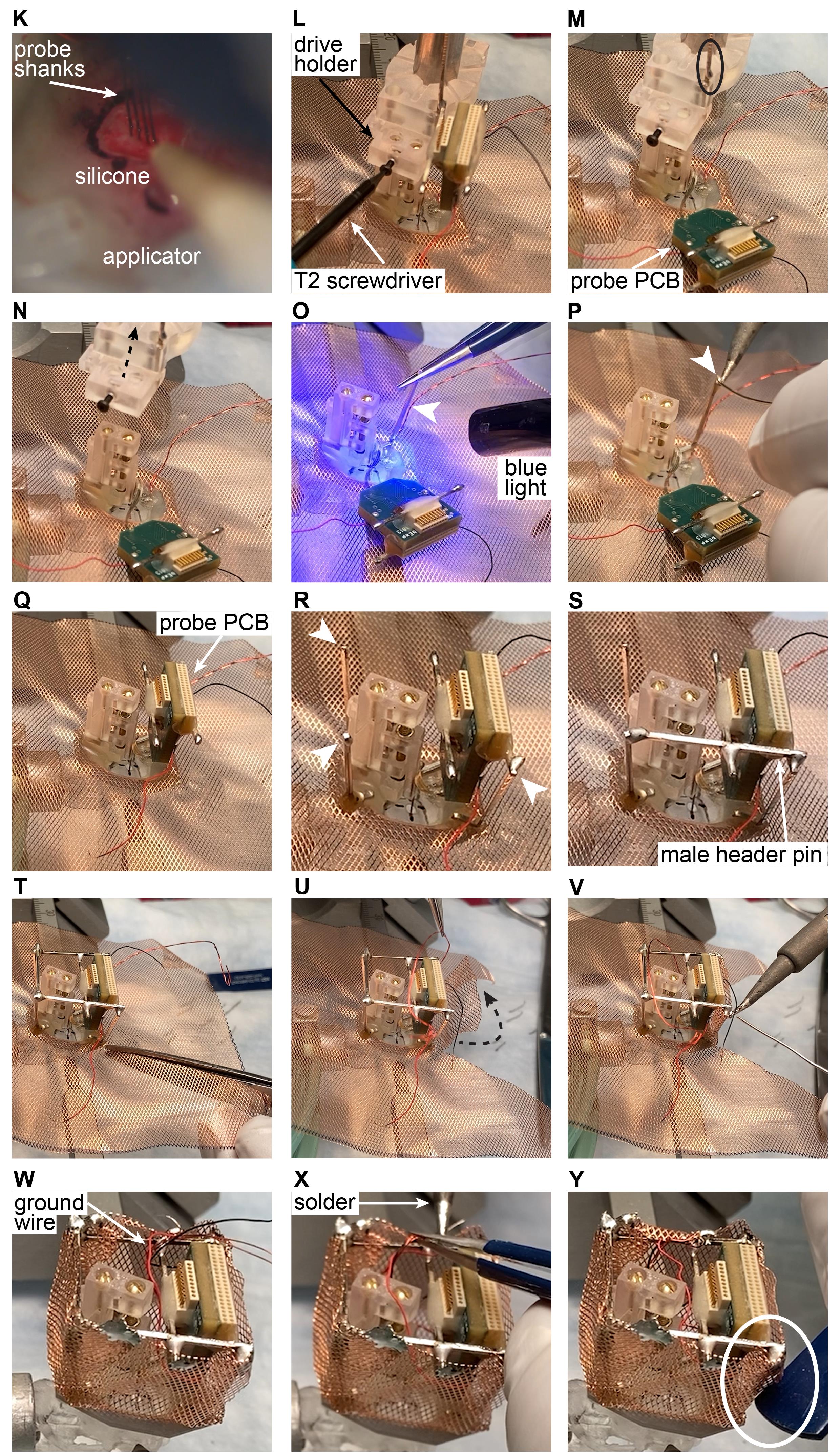
Figure 9. Silicone probe implantation in rodents (K-N) and cap building in mice (O-Y). The ‘surgery’ is performed on a 3D-printed mouse skull. Note that steps K-O are identical for mice and rats.Building a copper mesh cage for rats.
Cut the copper mesh along the diagonals, all the way to the plastic base (Figure 10O).
Repeat with the remaining three corners (Figure 10P).
Fold up the copper mesh and attach the pieces using solder (Figure 10Q).
Using the handle of a tweezer, smooth out the edges, if necessary (Figure 10R).
Critical step: Make sure there is no sharp edge around the plastic base.
Using scissors, cut the height of the copper mesh to the appropriate height all around (Figure 10S). Figure 10T shows the completed step.
Paint the outer surface of the copper mesh with relatively liquid dental cement using a large surface spatula (Figure 10U).
Critical step: Make sure that dental cement is not dripping onto the fur or the face of the rat. Make sure that the plastic base – copper mesh connection is properly covered (if not covered completely, it can introduce a lot of muscle artifacts).
Note: We recommend using Unifast Trad cement.
Cover the top of the copper mesh with dental cement (Figure 10V).
Note: Follow the instructions as shown in Figure 10U.
Steps are not shown in the Figure: solder the male header pin of the probe PCB to the copper mesh. Solder probe ground and wire of ground screw to the copper mesh.
Cover the top with CobanTM tape. Turn off the anesthesia and release the animal from the stereotaxis setup.
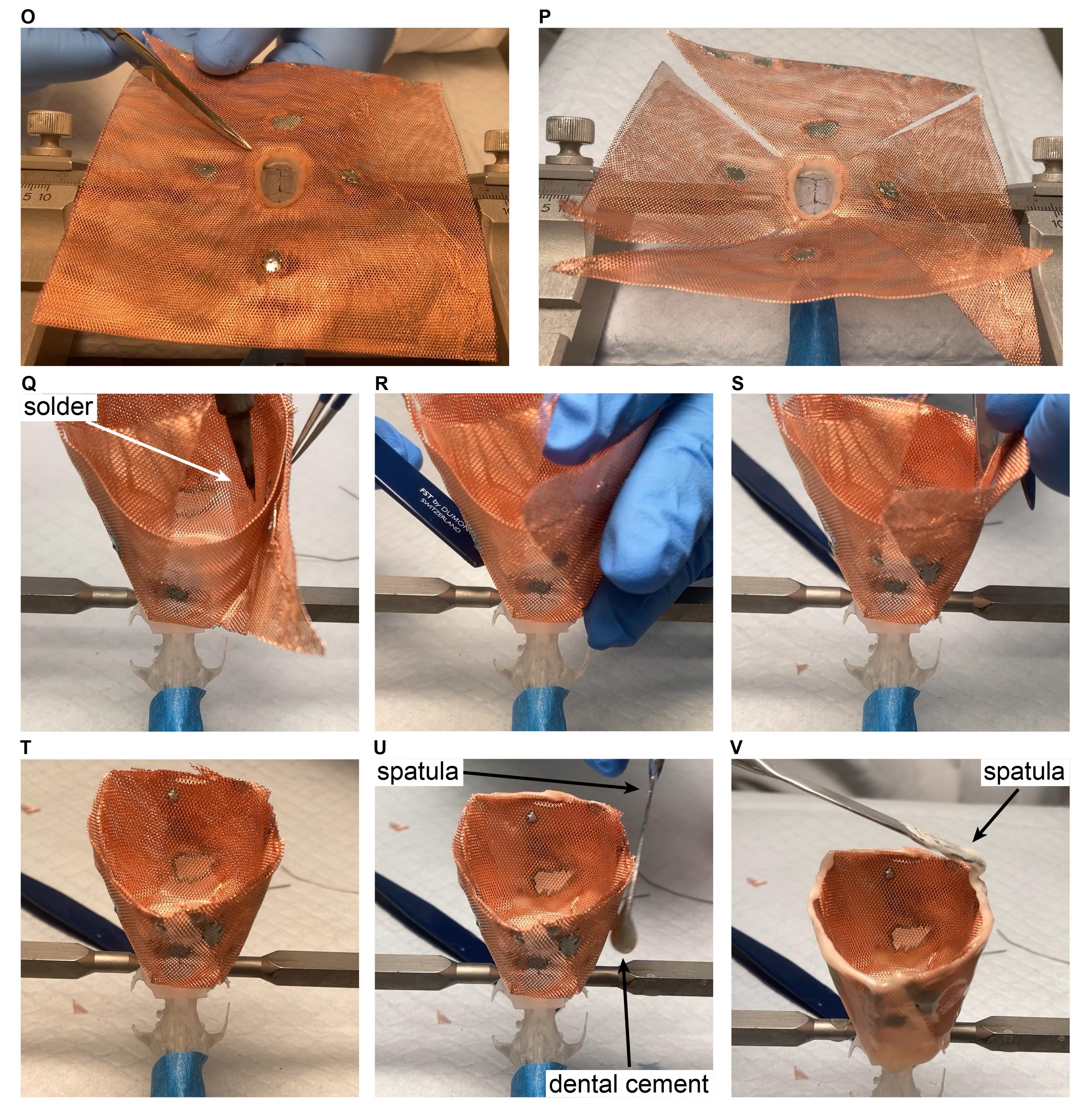
Figure 10. Cap building in rats. The ‘surgery’ is performed on a 3D-printed rat skull.Post anesthesia.
Weigh the animal again to determine the weight of the crown.
Put the animal in a home cage without bedding and place the cage on a heating pad the first night.
Inject Buprenex subcutaneously after 20 min (0.05-0.1 mg/kg).
General notes.
Apply mineral oil to the eyes of the animal at regular intervals.
To keep the animal hydrated for the first few days, provide an aqua-gel and a small container with water. Provide regular rodent pills.
Probe recovery procedure (Video 4 and Figure 11).
Align the drive holder with the drive using the stereotactic frame. Once the position is aligned in the x-y plane, move the drive holder down (Figure 11A, step 1). Next, secure the top of the drive with the screw located on the side of the drive holder (Figure 11A, step 2).
Critical step: Do not tighten the screw too strongly as the metal screw can break the plastic drive.
Loosen the back screw from the base (Figure 11B, step 1) and move the drive carefully upwards (Figure 11B, step 2).
Critical step: Monitor the shanks of the probe under the microscope during the entire recovery procedure and, if any unexpected movement of the probe is observed, return to the previous step to make sure that everything is secured properly.
Release the stereotax attachment from the stereotax arm and clean the probe. Store the probe attached to the stereotax attachment.
Note: The probe can be cleaned by initially rinsing it in distilled water, then contact lens solution (containing protease) and distilled water again; each washing step should last for at least 12 h. If extra tissue or debris is detected between the shanks, it can be removed by a fine needle under a microscope. Another way to clean the probe is by inserting it into 2-4% agarose gel a couple of times. This will push any debris away from the sites along the shanks.
Video 4. How to recover a silicon probe using a recoverable microdrive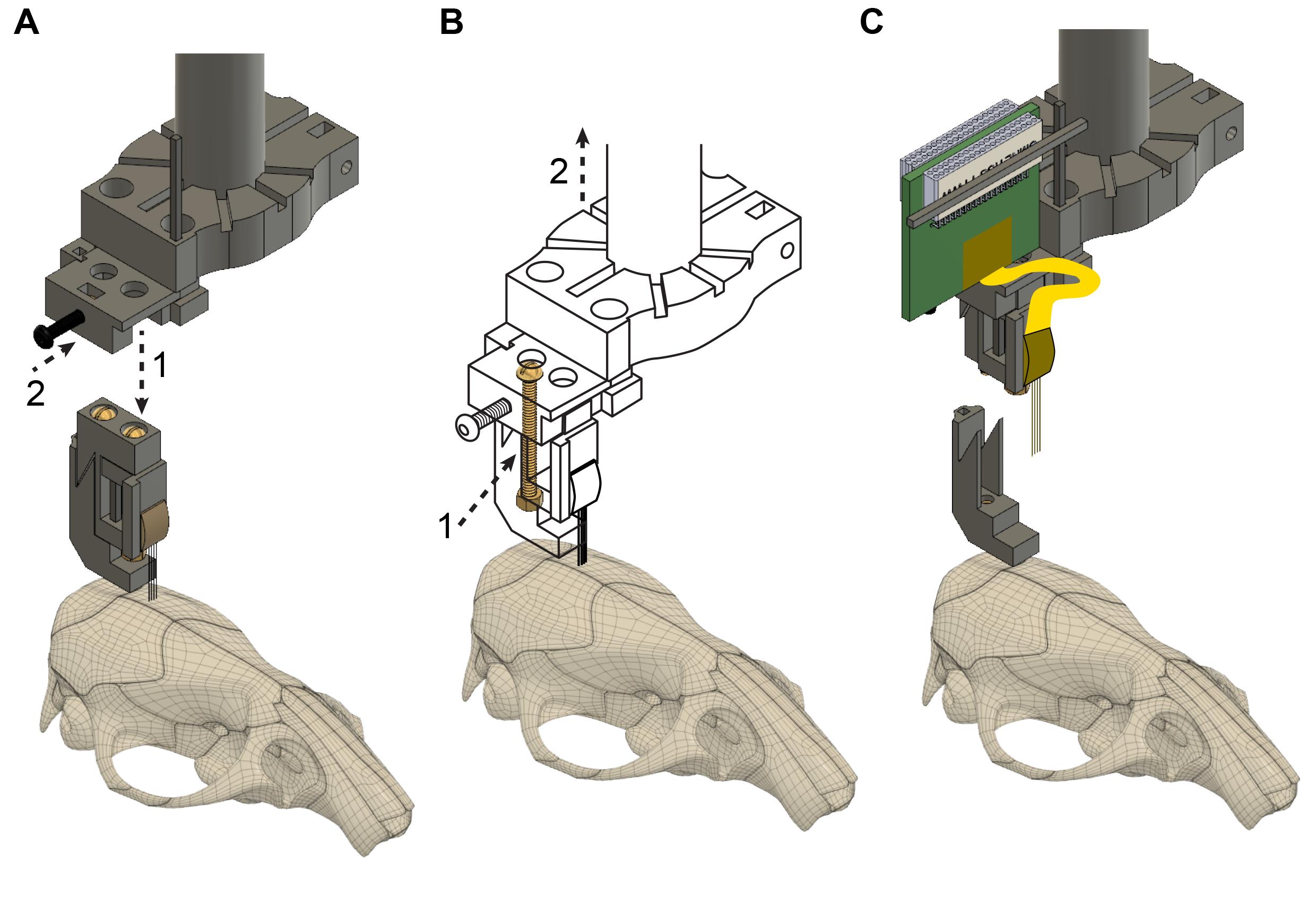
Figure 11. Probe recovery. A. The implantation tool is attached to the microdrive (step 1) and is fixed with the black screw (step 2). The flexible cable and Omnetics connector are not shown. B. The back screw is loosened completely (step 1), detaching the microdrive from the base; then, the implantation tool is raised using the stereotax manipulator (step 2), explanting the probe. C. The fully recovered microdrive and silicon probe with flexible cable and Omnetics connector. The probe shanks can be cleaned, and a new microdrive base can be attached, making the whole device ready for reimplantation in a new animal subject.
Figure 12, panels D-G show the wide applicability of the hybrid base for silicon probe recordings with temperature manipulations and optic fiber stimulation.
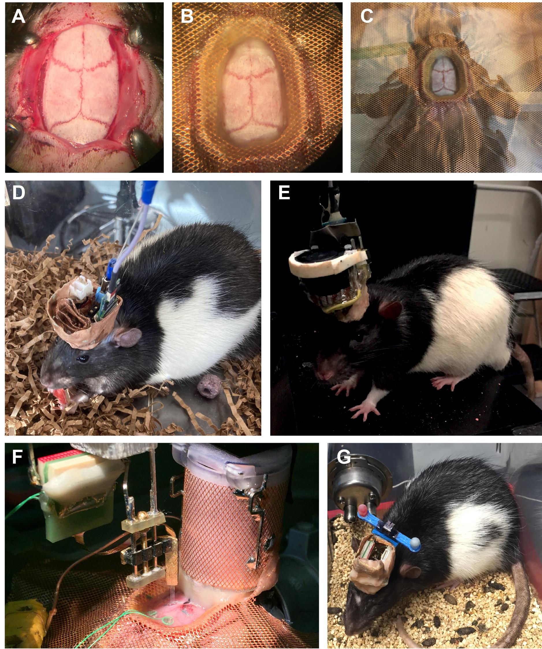
Figure 12. Applicability of the hybrid base. A. Exposed skull before the base is attached. B-C. Close up (B) and wide view (C) of the attached hybrid cap system. D. Peltier cooling device with passive cooling, thermistor, and silicon probes implanted at two different insertion sites. E. Peltier cooling device with an active 20 mm electric fan for cooling, thermocouple, wires, and silicon probe implants. F. Bilateral CA1 probe implants (shown during implantation of the left hemisphere implantation) with dry ice cooling chamber already implanted. G. Virus injected animal for optogenetic experiments. Four 50-µm diameter optic fibers were implanted with two diodes along with a silicon probe in CA1. Two diodes (blue bar) are attached for head position tracking via ceiling-mounted camera. Panels A-C and E-G from Petersen and Buzsáki (2020). Rat shown in panel D is from an ongoing unpublished study. All pictures are of Long Evans rats.
Notes
Members of our labs have performed invasive silicon probe implant surgeries on hundreds of rodents (mice and rats) just within the last year and have used variations of the base plate system for most of our probe implantations during the last few years. Based on individual estimates (of two rat and three mouse researchers), using the rat and mouse base system saves about 30-60 min during surgery. This time was originally spent on building the dental cement perimeter and the drilling craniotomies for anchoring skull screws and on attaching the copper mesh to this dental cement base ( Vandecasteele et al., 2012 ).
According to a recent internal survey based on about 25 silicon probes with the recoverable microdrive, on average, each probe was recovered two times and reimplanted successfully in new animal subjects. Out of 48 recovery attempts, only five failed. All users were able to recover silicon probes successfully if there was no surgery/time of implant-related complications. Coagulated blood, dried bone wax, or debris attached to the shanks were the most frequent causes of complication resulting in failed probe recovery. Before attempting a probe recovery in these cases, we recommend soaking the implanted silicon probe for at least 10 min in saline and removing as much debris beforehand as possible. The recovery procedure takes 30 min on average compared to 1-2 h ( Vandecasteele et al., 2012 ).
Acknowledgments
We would like to thank our early adaptors in Royer, Diba, and Buzsaki Labs for testing the microdrive and the baseplate and for providing feedback. We also thank Dmitry Rinberg for advice and feedback on designs. This work was supported by U19 NS107616, U19 NS104590, R01 MH122391, NeuroNex MINT (NSF 1707316), and The Lundbeck Foundation. The baseplate was developed for Petersen and Buzsaki (2020) and Voroslakos et al. (2020), and the microdrives were developed for Voroslakos et al. (2020).
Competing interests
E.Y. is co-founder of NeuroLight Technologies, a for-profit manufacturer of neurotechnology. The remaining authors have no conflict of interest.
Ethics
All experiments were approved by the Institutional Animal Care and Use Committee at New York University Medical Center.
References
- Chung, J., Sharif, F., Jung, D., Kim, S. and Royer, S. (2017). Micro-drive and headgear for chronic implant and recovery of optoelectronic probes. Sci Rep 7(1): 2773.
- Chung, J. E., Magland, J. F., Barnett, A. H., Tolosa, V. M., Tooker, A. C., Lee, K. Y., Shah, K. G., Felix, S. H., Frank, L. M. and Greengard, L. F. (2017). A Fully Automated Approach to Spike Sorting. Neuron 95(6): 1381-1394 e1386.
- Juavinett, A. L., Bekheet, G. and Churchland, A. K. (2019). Chronically implanted Neuropixels probes enable high-yield recordings in freely moving mice. Elife 8: e47188.
- Jun, J. J., Steinmetz, N. A., Siegle, J. H., Denman, D. J., Bauza, M., Barbarits, B., Lee, A. K., Anastassiou, C. A., Andrei, A., Aydin, C., Barbic, M., Blanche, T. J., Bonin, V., Couto, J., Dutta, B., Gratiy, S. L., Gutnisky, D. A., Hausser, M., Karsh, B., Ledochowitsch, P., Lopez, C. M., Mitelut, C., Musa, S., Okun, M., Pachitariu, M., Putzeys, J., Rich, P. D., Rossant, C., Sun, W. L., Svoboda, K., Carandini, M., Harris, K. D., Koch, C., O'Keefe, J. and Harris, T. D. (2017). Fully integrated silicon probes for high-density recording of neural activity. Nature 551(7679): 232-236.
- Luo, T. Z., Bondy, A. G., Gupta, D., Elliott, V. A., Kopec, C. D. and Brody, C. D. (2020). An approach for long-term, multi-probe Neuropixels recordings in unrestrained rats. Elife 9: e59716.
- Petersen, P. C. and Buzsáki, G. (2020). Cooling of Medial Septum Reveals Theta Phase Lag Coordination of Hippocampal Cell Assemblies. Neuron 107(4): 731-744 e733.
- Sariev, A., Chung, J., Jung, D., Sharif, F., Lee, J. Y., Kim, S. and Royer, S. (2017). Implantation of Chronic Silicon Probes and Recording of Hippocampal Place Cells in an Enriched Treadmill Apparatus. J Vis Exp(128): 56438.
- Schoonover, C. E., Ohashi, S. N., Axel, R. and Fink, A. J. P. (2021). Representational drift in primary olfactory cortex. Nature 594(7864): 541-546.
- Steinmetz, N. A., Aydin, C., Lebedeva, A., Okun, M., Pachitariu, M., Bauza, M., Beau, M., Bhagat, J., Bohm, C., Broux, M., Chen, S., Colonell, J., Gardner, R. J., Karsh, B., Kloosterman, F., Kostadinov, D., Mora-Lopez, C., O'Callaghan, J., Park, J., Putzeys, J., Sauerbrei, B., van Daal, R. J. J., Vollan, A. Z., Wang, S., Welkenhuysen, M., Ye, Z., Dudman, J. T., Dutta, B., Hantman, A. W., Harris, K. D., Lee, A. K., Moser, E. I., O'Keefe, J., Renart, A., Svoboda, K., Hausser, M., Haesler, S., Carandini, M. and Harris, T. D. (2021). Neuropixels 2.0: A miniaturized high-density probe for stable, long-term brain recordings. Science 372(6539): eabf4588.
- Vandecasteele, M., M, S., Royer, S., Belluscio, M., Berenyi, A., Diba, K., Fujisawa, S., Grosmark, A., Mao, D., Mizuseki, K., Patel, J., Stark, E., Sullivan, D., Watson, B. and Buzsaki, G. (2012). Large-scale recording of neurons by movable silicon probes in behaving rodents. J Vis Exp(61): e3568.
- Vöröslakos, M., Petersen, P. C., Vöröslakos, B. and Buzsaki, G. (2021). Metal microdrive and head cap system for silicon probe recovery in freely moving rodent. Elife 10: e65859.
- Wu, F., Stark, E., Ku, P. C., Wise, K. D., Buzsaki, G. and Yoon, E. (2015). Monolithically Integrated muLEDs on Silicon Neural Probes for High-Resolution Optogenetic Studies in Behaving Animals. Neuron 88(6): 1136-1148.
Article Information
Publication history
Accepted: May 26, 2021
Published: Aug 20, 2021
Copyright
![]() Vöröslakos et al. This article is distributed under the terms of the Creative Commons Attribution License (CC BY 4.0).
Vöröslakos et al. This article is distributed under the terms of the Creative Commons Attribution License (CC BY 4.0).
How to cite
Readers should cite both the Bio-protocol article and the original research article where this protocol was used:
- Vöröslakos, M., Miyawaki, H., Royer, S., Diba, K., Yoon, E., Petersen, P. C. and Buzsáki, G. (2021). 3D-printed Recoverable Microdrive and Base Plate System for Rodent Electrophysiology. Bio-protocol 11(16): e4137. DOI: 10.21769/BioProtoc.4137.
- Vöröslakos, M., Petersen, P. C., Vöröslakos, B. and Buzsaki, G. (2021). Metal microdrive and head cap system for silicon probe recovery in freely moving rodent. Elife 10: e65859.
Category
Biological Engineering > Bioprinting
Neuroscience > Basic technology
Do you have any questions about this protocol?
Post your question to gather feedback from the community. We will also invite the authors of this article to respond.
![]() Tips for asking effective questions
Tips for asking effective questions
+ Description
Write a detailed description. Include all information that will help others answer your question including experimental processes, conditions, and relevant images.