
- Submit a Protocol
- Receive Our Alerts
- EN

- Protocols

- Articles and Issues
- For Authors
- About
- Become a Reviewer

Live Imaging of Phagoptosis in ex vivo Drosophila Testis
Published: Vol 13, Iss 6, Mar 20, 2023 DOI: 10.21769/BioProtoc.4637 Views: 587
Reviewed by: Gal HaimovichRafael Sênos DemarcoRajesh D GunageAnonymous reviewer(s)
Original research article
The authors used this protocol in:

Jun 2022

Protocol Collections
Comprehensive collections of detailed, peer-reviewed protocols focusing on specific topics

Related protocols
Abstract
Phagoptosis is a prevalent type of programmed cell death (PCD) in adult tissues in which phagocytes non-autonomously eliminate viable cells. Therefore, phagoptosis can only be studied in the context of the entire tissue that includes both the phagocyte executors and the targeted cells doomed to die. Here, we describe an ex vivo live imaging protocol of Drosophila testis to study the dynamics of phagoptosis of germ cell progenitors that are spontaneously removed by neighboring cyst cells. Using this approach, we followed the pattern of exogenous fluorophores with endogenously expressed fluorescent proteins and revealed the sequence of events in germ cell phagoptosis. Although optimized for Drosophila testis, this easy-to-use protocol can be adapted to a wide variety of organisms, tissues, and probes, thus providing a reliable and simple means to study phagoptosis.
Background
Several types of programmed cell death (PCD) have been described, all of which function to eliminate excess or damaged cells throughout development and to maintain tissue homeostasis in adult organisms (Fuchs and Steller, 2011). Phagoptosis, a newly recognized type of PCD, is a form of cell non-autonomous cannibalism in which one cell uses the phagocytic machinery to induce death and degradation of a nearby cell that would otherwise remain alive [(Brown and Neher, 2012); Figure 1A]. Accordingly, inhibiting the phagocytic machinery within phagocytes prevents the death of targeted cells. In adults, phagoptosis is the most prevalent form of PCD, mediating the turnover of several abundant short-lived cells, including erythrocytes (Olsson and Oldenborg, 2008) and neutrophils (Jitkaew et al., 2009). This important process was only recently recognized because it can occur only in the context of entire tissues that include the two cell types, i.e., phagocytes and targeted live cells. Therefore, developing assays and finding biomarkers for this process represents a major step in characterizing the process and identifying the regulators of phagoptosis.

Figure 1. Phagoptosis of germ cell progenitors. A. The mechanism of phagoptosis. A phagocyte (pink) engulfs a live-targeted cell (green), creating a phagosome around that target, and recruits the phagocytic machinery (Rab5, Rab7, Lamp1, and lysosomes) to degrade its contents. B. Schematic representation of the apical tip of the Drosophila testis (side view). Germline (green) and cyst (pink) stem cells surround the hub cells (gray). Approximately a quarter of the spermatogonia progenitors (green) undergo spontaneous phagoptosis (red) by neighboring phagocytic cyst cells (pink). Dashed line separates progenitors from terminally differentiated spermatocytes.
In the Drosophila testis, as many as a quarter of newly emerging spermatogonia progenitors are spontaneously eliminated by germ cell death (GCD) ( Yacobi-Sharon et al., 2013; Napoletano et al., 2017). We recently showed that the underlying mechanism of GCD is phagoptosis (Zohar-Fux et al., 2022). The cyst cells that surround the germ cell progenitors rely on the phagocytic machinery to induce death and degradation of targeted germ cells (Figure 1B).
Several fluorescent markers can be used to mark the phagocytic cyst cells during the live imaging protocol, including cytoplasmic green fluorescent protein (cytGFP; Figure 2 and Video 1) or membrane-targeted CD8-GFP (Lee and Luo, 1999)]. To follow the activity of the cyst cell–derived phagocytic machinery, we used yellow fluorescent protein (YFP) tags inserted at the DNA level at the endogenous chromosomal loci of Rab5- and Rab7-containing endosomes [Video 2 (Dunst et al., 2015)]. During live imaging, we maintain the testes in a medium containing a low concentration of LysoTracker and Hoechst to visualize in situ changes in lysosomal activity and DNA integrity, respectively. Intriguingly, this technique revealed the formation of large blebs pinching off the dying germ cells that were not detected in fixed samples. While the surfaces of these blebs were positive for LysoTracker, their inner content was negative for such staining, suggesting that nutrients of the dying germ cells are transported to the cyst cells via these blebs [Video 2 (Zohar-Fux et al., 2022)]. In this protocol, we dissect whole-mount intact testes and visualize the spontaneously occurring phagoptosis process for 4–12 hours. Since the testis is a highly regenerative tissue and the germline stem and progenitor cells divide frequently, the entire tissue throbs, which may affect imaging resolution. Therefore, tight adherence of the testis to the chamber without damaging its integrity is the most critical step in obtaining a detailed live imaging movie. A previous live imaging protocol designed to study the stem cell niche of the Drosophila testis suggested the use of the isotonic Ringer's solution as the dissection medium (Greenspan and Matunis, 2017). Indeed, using Ringer's solution significantly improves the ability of the light testis to sink to the bottom of the coverslip and facilitates the adherence process.
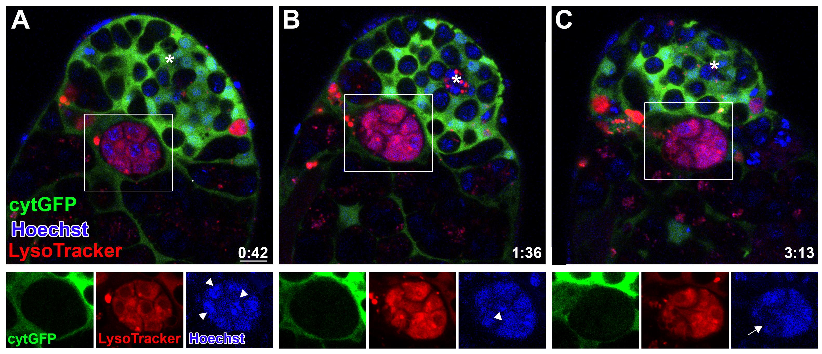
Figure 2. Phagoptosis of germ cell progenitors. A-C. Snapshots of live-imaged testis, marked with LysoTracker (red), Hoechst (blue, nuclei), and GFP (cyst cells, c587Gal4;UAS-cytGFP). Time (hour:min) is shown on the bottom right corner. Note the rectangles and bottom images (single-channel views of the boxed regions) highlighting a phagoptosis event. White arrowheads mark DNA packed into separate nuclei (A and B) that are further involuted into one bundle (C, arrow). Asterisks mark the hub, and scale bars correspond to 10 μm.
In developing this protocol, we tested several adherence methods, including the use of 0.1% gelatin, Concanavalin A (Con A, 100 ng/mL), double layers of Con A and fetal calf serum (FCS; 10%), and two concentrations of Poly-L-Lysine (0.01% and 0.1%). We found that the dissected testes could be adhered only on Poly-L-Lysine and that the higher concentration of Poly-L-Lysine (0.1%) enabled easy adherence without applying excessive force that could damage the tissue. Coating the dish with poly-L-lysine for immobilization was shown to be detrimental to the development of early germ line cysts (Gartner et al., 2014).
Materials and Reagents
Eppendorf tubes
10 µL pipettor
Poly L-Lysine solution, 0.1% (w/v) in H2O (Sigma-Aldrich, catalog number: P8920)
Fetal bovine serum (Biological Industries, catalog number: 04-007-1A)
Penicillin/streptomycin (Biological Industries, catalog number: 03-031-1B)
Schneider’s Drosophila medium (Biological Industries, catalog number: 01-150-1A)
Hoechst stain (Invitrogen, catalog number: H3570)
LysoTracker (Thermo Fisher Scientific, catalog number: L7528)
Immersion oil (Nikon, catalog number: M210009219)
Dulbecco's phosphate buffered saline (PBS, 10×) (Biological Industries, catalog number: 02-023-5A)
Sodium chloride (NaCl) (Sigma-Aldrich, catalog number: S9888-500G)
Potassium chloride (KCl) (Sigma-Aldrich, catalog number: P3911-500G)
Calcium chloride (CaCl2) (Sigma-Aldrich, catalog number: C1016-500G)
Magnesium chloride (MgCl2) (Sigma-Aldrich, catalog number: M8266-100G)
Sucrose (Sigma-Aldrich, catalog number: S0389-500G)
HEPES solution (1 M, pH 6.9) (Sigma-Aldrich, catalog number: H0887-20ML)
Schneider’s medium (see Recipes)
Ringer’s solution (see Recipes)
Equipment
Standard fly husbandry equipment (e.g., vials with freshly prepared standard cornmeal molasses agar medium, 25 °C incubators, CO2 and fly pad station to anaesthetize flies, and brushes to sort and transfer the flies)
Chambered coverslip containing eight wells (ibidi, catalog number: 80826; Figure 3A)
Superfrost microscope slides (Thermo Scientific, catalog number: 631-0705). A superfrost slide is used as a dissecting dish and can be re-used after cleaning with 70% ethanol.
Dumont #5 blunter forceps (e.g., Fine Science Tools, catalog number: 11252-20)
Dumont #55 sharper forceps (e.g., Fine Science Tools, catalog number: 11255-20)
Zooming stereomicroscope with 5 × 40 magnification (e.g., Carl Zeiss, model: STEMI SV 11)
Confocal microscope. (e.g., Nikon A1R inverted laser scanning confocal microscope with a Plan Apochromat VC 60× oil objective)
Biological safety cabinet (hood) (e.g., ESCO, model: AC2-4S1)
Software
Microscope controller software (e.g., Nikon NIS Elements C v. 4.2 software, https://www.microscope.healthcare.nikon.com/products/software/nis-elements)
Cell imaging software (e.g., Imaris for Cell Biologists, Oxford Instruments, https://imaris.oxinst.com/)
ImageJ/FIJI https://imagej.net/downloads
Procedure
Schneider’s medium
In a biological safety cabinet (hood), prepare Drosophila tissue culture medium (0.5 L): 10% (v/v) fetal bovine serum and 0.5% penicillin/streptomycin in Schneider’s medium.
Prepare 600 µL aliquots of the medium in Eppendorf tubes and keep the medium bottle and aliquots at 4 °C. On the day of the experiment, transfer one aliquot to room temperature (RT).
Ringer's solution
Prepare 50 mL of Ringer's solution. The testes sink easily in the isotonic Ringer's solution, which facilitates the adherence process.
Divide the Ringer’s solution into 200 µL aliquots in Eppendorf tubes and keep at 4 °C. On the day of the experiment, transfer one aliquot to RT.
Coverslip coating
Cover the chambered coverslip containing eight wells with 300 µL per well of 0.1% Poly L-Lysine for 40 min at RT or overnight at 4 °C.
Collect the Poly L-Lysine back into an Eppendorf tube for re-use. Remove traces of Poly L-Lysine with a 10 µL pipettor and leave the coverslip to completely dry on the bench (~1 h). The coated chambered coverslip can be kept until all the wells are used.
Fly husbandry
Prepare the genotype/conditions being tested (e.g., starvation and/or aging). Obtain the appropriate transgenic line (e.g., rab5-YFP or rab7-YFP; Video 2) or establish the crosses that yield male flies expressing the appropriate fluorescent marker in the desired genetic background [e.g., to mark cyst cells with GFP (Video 1), we generated the cross c587Gal4;UAS-cytGFP].
Collect 5–6 offspring males from the desired genotype and maintain them for 2–3 days before the experiments. Phagoptosis is less abounded in 1-day-old flies and appears in all testes dissected from 2–3-day-old males or older.
 Video 1. Cyst cells marked with cytGFP. A representative example of live, ex vivo young Drosophila testis is labeled with LysoTracker (red) and Hoechst (blue, nuclei). Scale bars represent 10 µm; time (hour:min) is shown on the bottom of the movie and single channels are presented in grayscale. Cyst cells are marked with cytGFP (green, c587Gal4;UAS-cytGFP). Arrow marks a phagoptosis event. Note the packed DNA in separate nuclei that becomes involuted into one bundle. Video 2. Rab7-YFP. Live-imaged testis from Rab7-YFP (green) labeled with LysoTracker (red). Scale bars represent 10 µm; time (hour:min) is shown on the bottom of the movie and single channels are presented in grayscale. Arrow marks late endosome vesicles surrounding phagotosed germ cells and recycle blebs. Arrowhead marks a new phagoptosis event that initiates after 1 h and 20 min.
Dissection of whole-mount adult testes and mounting (see Video 3)
Video 3. Dissection of whole-mount adult testes. Forceps handling in testes dissection. The circle marks a separated pair of coiled coil testesPrepare Ringer's solution with Hoechst stain and LysoTracker (RHL solution). First, prepare Hoechst stock solution of 10 mg/mL (dissolved in water) and a LysoTracker stock solution of 1:10 diluted in PBS (1 µM, can be kept for one week at 4 °C). Add 1 µL of the LysoTracker stock solution (0.03 µM, final concentration) and 0.5 µL of Hoechst stock solution (0.3 µM, final concentration) to the 200 µL Ringer's solution aliquot and maintain at RT. This final RHL solution can be used only on the day of the experiment.
Transfer one aliquot (600 µL) of Schneider’s medium to RT.
Clean the two forceps (#5 and #55), superfrost microscope slide, and CO2 pad with 70% ethanol before dissecting.
Anesthetize adult flies using CO2. Using the stereomicroscope, collect 5–6 males with a paintbrush and leave them on the pad to be dissected.
Under moderate magnification (10×) of the stereomicroscope, add a drop of 50 µL of RHL solution onto the superfrost microscope slide and avoid liquid dispersion. Use the blunter forceps in your non-dominant hand to gently transfer one male from the CO2 pad into the drop of RHL solution. Lay the fly on its back or side and keep holding it gently, submerged in the RHL solution. Use the sharper forceps in your dominant hand to gently tear and grab the cuticle near the bottom of the male's abdomen to release the testes into the RHL solution. Hold the posterior cuticle that contains the testes with the blunter forceps and gently pull with the sharper forceps, until you separate the pair of coiled coil testes (Video 3). Discard the rest of the fly and dissect a second male.
Add 10 μL of RHL solution to one of the eight wells of the Poly L-Lysine-coated chambered coverslip (Figure 3A). Use one prong of the forceps to transfer the dissected testes from the slide dish to the drop in the chamber (Figure 3B–3C). Use one prong of the #5 blunter forceps to gently pull each testis from its basal edge to open the coiled shape, so as to adhere the sample to the bottom of the well and expose the apical tip without damaging the tissue (Figure 3D). Damaged samples should be removed to avoid affecting the intact samples by death signals.
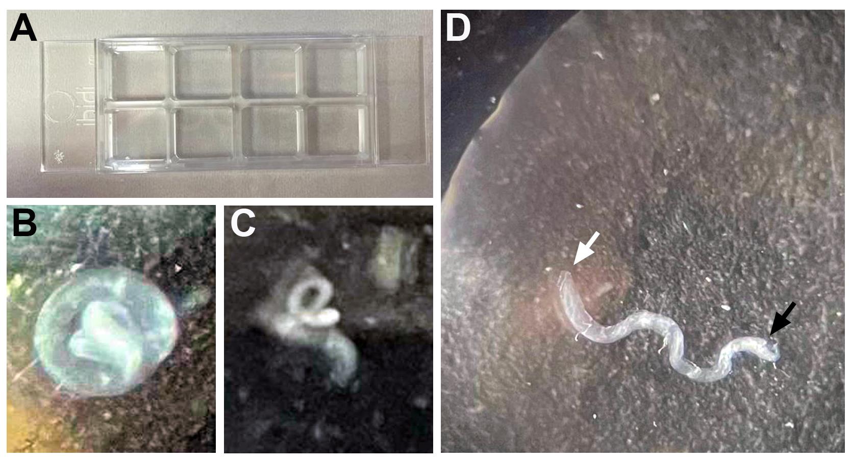
Figure 3. Testis mounting. A. Poly L-Lysine-coated chambered coverslip containing eight wells. B–C. Dissected testis in one well containing 10 μL of RHL solution can appear as a completely (B) or partially (C) coiled coil. D. White and black arrows mark the apical and basal edges of the testis, respectively. Pulling the testis from its basal edge with one prong of the forceps adheres the testis to the bottom of the well and exposes the apical tip for live imaging.Repeat steps E5 and E6 to obtain a total of two wells, each containing four testes. The rest of the wells can be left empty for the next experiment.
Gently add 300 μL of Schneider’s medium to the corner of the well to avoid detachment of the samples. Cover the chambered coverslip with the lid and proceed to the confocal microscope. Live imaging is performed at RT. At the end of the experiment (after live imaging is completed), add 70% ethanol to the used wells to prevent contamination and allow subsequent use of the empty wells for the next experiment.
Time-lapse confocal imaging
Use confocal or spinning disk imaging system (the protocol can be adapted for virtually any imaging setup). We used a Nikon A1R laser scanning confocal inverted microscope equipped with four lasers (406, 492, 561, and 639 nm), a detector unit with four normal PMTs (four channels), a galvano scanner, a motorized XYZ stage, a widefield fluorescence module, a cMOS camera and NIS Elements C software, and a 60× (NA = 1.4, Plan Apo VC) oil immersion objective.
Turn on the system and place the 8-well coated chambered coverslip on the stage. Use the eye piece and widefield fluorescence to find intact testes with the low magnification objective (10×). Take widefield images using the capture function of the camera for each of the eight testes in order to later locate and examine each sample at 60× and to pick the desired one for final time-lapse imaging.
Lower the 10× objective and swap it to 60× objective and apply immersion oil on it. Find all the eight testes in captured images and direct the stage to relocate there automatically. Pick the testis that is best adhered, shows strong GFP, LysoTracker, and Hoechst signals, and is undamaged. Raise the objective back and fine tune the focus. Switch from widefield mode to confocal.
Set the imaging parameters or reuse from a previously saved image file. We use NIS Elements C v. 4.2 software, and the following parameters are implemented to image phagoptosis in live Drosophila testis.
Open the Dye and Spectral Setting (Filter and Dye) window (Figure 4).
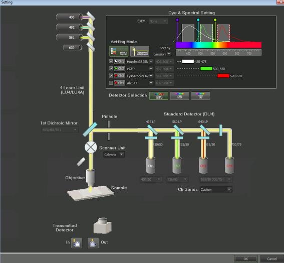
Figure 4. Filter and Dye window
Choose settings as follows:Setting Mode: Auto
Ch1 (excitation laser 406 nm, filter 425–475 nm) for Hoechst, Ch2 (excitation laser 492 nm, filter 500–550 nm) for GFP, and Ch3 (excitation laser 562, filter 570–620) for LysoTracker Red.
Scanner Unit: Galvano
Detector: Standard Detector (DU4)
Pseudocolor can be chosen for each channel by pressing the channel button.
Open ND Acquisition window for adjusting Z-stack range and time-lapse settings (Figure 5).
For Z-stack imaging, check the Z tab, choose left option of Define Top Bottom. Choose the Top and Bottom positions by using the focus roller while in Find Mode scanning (Figure 6; a quick scan) and pressing Top and Bottom buttons when wanted positions are reached.
Check Save to File and set the Path for automatic file storing.
Set the step to 3 μm.
For time-lapse imaging, check Time tab, check a Phase, and set the Interval (3 min) and Duration (6–12 h).
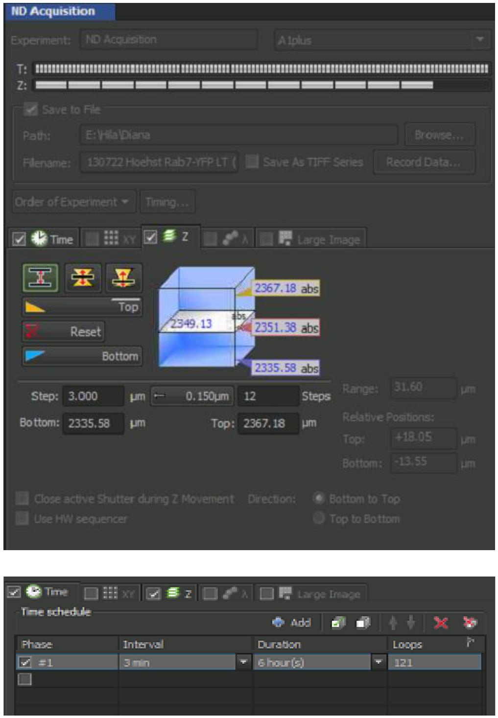
Figure 5. ND Acquisition windowOpen A1plus Settings window for confocal adjustment for final imaging (Figure 6).
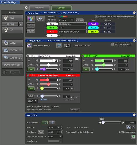
Figure 6. A1plus Settings windowScan Setting:
Scan Direction: line by line
Scan Size: 1024 × 1024 pixels
Scan Speed: 0.125 (Pixel Dwell = ~6 microsecond).
Line Average/Integrate: None
Zoom: 1
Acquisition:
Set pinhole to 1.2.
Adjust the settings for each channel separately in Live mode scanning to get the appropriate image (in this mode, the scanning is performed according to the final parameters listed above).
It is recommended to minimize the laser power as much as possible to avoid photodamage and photobleaching. If the signal is good, adjusting HV (High Voltage, Gain) will be enough to reach the best image quality. Offset is used to reduce the background if needed (it should be done cautiously to avoid signal reduction).
While adjusting the channels Acquisition settings, Saturation indicator should be on to avoid oversaturated pixels.
Go back and forth within the Z-stack range, using the focus roller or clicking within the range in ND acquisition window (Z tab), to ensure the adjustment of each channel setting is balanced for all focal planes.
To start acquiring Z-stack with Time-lapse images, press “Run now” at the bottom of ND acquisition window.
Data analysis
The obtained images can be analyzed in any software of choice. Here, we first used Imaris and then ImageJ/FIJI.
Convert the microscope file to an Imaris file using Imaris File Converter 9.8.2.
Hold right mouse click to rotate the testis to point up apical edge of the testis.
Choose the specific Z-slice that best shows your immunofluorescence staining. Use: Edit → Crop 3D → Select the Z-Slice.
Zoom in to the part you are interested in.
Start recording the time series by pressing the Record function. Record different movies for each separate and merged channel.
Save the movies you have recorded as type: H.264 Movie (*.mp4).
Use the software ImageJ to generate a movie that shows a panel representing separate and merged channels.
Import the movies you have recorded by using: File → Import → Movie.
Combine all the movies together to create a panel by using: Image → Stacks → Tools → Combine.
Save the last panel movie of all channels together: frame rate: 10, format: mp4, and codec H.264.
Notes
To label cyst cells with cytGFP, we crossed females of c587Gal4 driver (on the X chromosome, T. Xie, Stowers Institute of Biomedical Research) that drives expression in early cyst cells with UAS-cytGFP males (c587Gal4;UAS-cytGFP). Rab5-YFP or Rab7-YFP (B. Lemaitre, EPFL) express YFP tags that were inserted at the DNA level at the endogenous chromosomal loci of Rab5- and Rab7-containing endosomes (Dunst et al., 2015). Flies and crosses were raised at 25 °C on freshly prepared standard cornmeal molasses agar medium. In addition, any fluorescent tagged proteins that are expressed in germ and/or cyst cells can be used to follow the GCD process.
Quantification of DNA (Hoechst) and phagosome (LysoTracker) volumes can be drawn from the movies, using Imaris (Bitplane) software with an appropriate iso-surfacing threshold.
This protocol can be adapted to other tissues that consist of both the phagocytes and the targeted cells, and that require the combination of genetic labeling of the phagocytes and the use of LysoTracker and Hoechst to establish the kinetic of events.
Recipes
Schneider's medium
0.5 L Schneider’s medium
10% (v/v) fetal bovine serum
0.5% penicillin/streptomycin in Schneider’s medium
Ringer's solution
128 mM NaCl
2 mM KCl
1.8 mM CaCl2
4 mM MgCl2
35.5 mM sucrose
5 mM HEPES, pH 6.9
Acknowledgments
This work was funded by the Israel Science Foundation (207/20). We thank A. Kolpakov for helping with the protocol setup and B. Lemaitre for the gracious gifts of Drosophila stocks. This protocol is derived from Zohar-Fux et al. (2022).
Competing interests
The authors declare that they have no competing interests.
References
- Brown, G. C. and Neher, J. J. (2012). Eaten alive! Cell death by primary phagocytosis: 'phagoptosis'. Trends Biochem Sci 37(8): 325-332.
- Dunst, S., Kazimiers, T., von Zadow, F., Jambor, H., Sagner, A., Brankatschk, B., Mahmoud, A., Spannl, S., Tomancak, P., Eaton, S., et al. (2015). Endogenously tagged rab proteins: a resource to study membrane trafficking in Drosophila. Dev Cell 33(3): 351-365.
- Fuchs, Y. and Steller, H. (2011). Programmed cell death in animal development and disease. Cell 147(4): 742-758.
- Gartner, S. M., Rathke, C., Renkawitz-Pohl, R. and Awe, S. (2014). Ex vivo culture of Drosophila pupal testis and single male germ-line cysts: dissection, imaging, and pharmacological treatment. J Vis Exp (91): 51868.
- Greenspan, L. J. and Matunis, E. L. (2017). Live Imaging of the Drosophila Testis Stem Cell Niche. Methods Mol Biol 1463: 63-74.
- Jitkaew, S., Witasp, E., Zhang, S., Kagan, V. E. and Fadeel, B. (2009). Induction of caspase- and reactive oxygen species-independent phosphatidylserine externalization in primary human neutrophils: role in macrophage recognition and engulfment. J Leukoc Biol 85(3): 427-437.
- Lee, T. and Luo, L. (1999). Mosaic analysis with a repressible cell marker for studies of gene function in neuronal morphogenesis. Neuron 22(3): 451-461.
- Napoletano, F., Gibert, B., Yacobi-Sharon, K., Vincent, S., Favrot, C., Mehlen, P., Girard, V., Teil, M., Chatelain, G., Walter, L., Arama, E. and Mollereau, B. (2017). p53-dependent programmed necrosis controls germ cell homeostasis during spermatogenesis. PLoS Genet 13(9): e1007024.
- Olsson, M. and Oldenborg, P. A. (2008). CD47 on experimentally senescent murine RBCs inhibits phagocytosis following Fcgamma receptor-mediated but not scavenger receptor-mediated recognition by macrophages. Blood 112(10): 4259-4267.
- Yacobi-Sharon, K., Namdar, Y. and Arama, E. (2013). Alternative germ cell death pathway in Drosophila involves HtrA2/Omi, lysosomes, and a caspase-9 counterpart. Dev Cell 25(1): 29-42.
- Zohar-Fux, M., Ben-Hamo-Arad, A., Arad, T., Volin, M., Shklyar, B., Hakim-Mishnaevski, K., Porat-Kuperstein, L., Kurant, E. and Toledano, H. (2022). The phagocytic cyst cells in Drosophila testis eliminate germ cell progenitors via phagoptosis. Sci Adv 8(24): eabm4937.
Article Information
Publication history
Published: Mar 20, 2023
Copyright
© 2023 The Author(s); This is an open access article under the CC BY-NC license (https://creativecommons.org/licenses/by-nc/4.0/).
How to cite
Readers should cite both the Bio-protocol article and the original research article where this protocol was used:
- Kanaan, D., Shklyar, B., Porat-Kuperstein, L. and Toledano, H. (2023). Live Imaging of Phagoptosis in ex vivo Drosophila Testis. Bio-protocol 13(6): e4637. DOI: 10.21769/BioProtoc.4637.
- Zohar-Fux, M., Ben-Hamo-Arad, A., Arad, T., Volin, M., Shklyar, B., Hakim-Mishnaevski, K., Porat-Kuperstein, L., Kurant, E. and Toledano, H. (2022). The phagocytic cyst cells in Drosophila testis eliminate germ cell progenitors via phagoptosis. Sci Adv 8(24): eabm4937.
Category
Cell Biology > Cell imaging > Confocal microscopy
Developmental Biology > Reproduction
Cell Biology > Tissue analysis > Tissue imaging
Do you have any questions about this protocol?
Post your question to gather feedback from the community. We will also invite the authors of this article to respond.
![]() Tips for asking effective questions
Tips for asking effective questions
+ Description
Write a detailed description. Include all information that will help others answer your question including experimental processes, conditions, and relevant images.