
- Submit a Protocol
- Receive Our Alerts
- EN

- Protocols

- Articles and Issues
- For Authors
- About
- Become a Reviewer

Application of Electrical Stimulation to Enhance Axon Regeneration Following Peripheral Nerve Injury
Published: Vol 13, Iss 19, Oct 5, 2023 DOI: 10.21769/BioProtoc.4833 Views: 160
Reviewed by: Alessandro DidonnaAnand Ramesh PatwardhanZheng Zachory Wei
Original research article
The authors used this protocol in:
May 2021

Protocol Collections
Comprehensive collections of detailed, peer-reviewed protocols focusing on specific topics


Related protocols
Abstract
Enhancing axon regeneration is a major focus of peripheral nerve injury research. Although peripheral axons possess a limited ability to regenerate, their functional recovery is very poor. Various activity-based therapies like exercise, optical stimulation, and electrical stimulation as well as pharmacologic treatments can enhance spontaneous axon regeneration. In this protocol, we use a custom-built cuff to electrically stimulate the whole sciatic nerve for an hour prior to transection and repair. We used a Thy-1-YFP-H mouse to visualize regenerating axon profiles. We compared the regeneration of axons from nerves that were electrically stimulated to nerves that were not stimulated (untreated). Electrically stimulated nerves had longer axon growth than the untreated nerves. We detail how variations of this method can be used to measure acute axon growth.
Keywords: Peripheral nerve injuryBackground
Peripheral nerve injury is an important clinical problem; generally, the functional recovery is very poor (Lee and Wolfe, 2000; Höke and Brushart, 2010; Enax-Krumova et al., 2017; Bulut et al., 2018; Zheng et al., 2018; Wang et al., 2019) if the injury is more proximal to the spinal cord, involves a gap of ≥ 5 mm, or involves mixed sensory and motor nerves. The main reason for this poor recovery is that the injured neurons are required to regenerate their axons over long distances, sometimes many centimeters, to reconnect to their peripheral target. The regenerating axons have a very slow rate of growth of ∼1 mm/day (Sulaiman and Gordon, 2000 and 2013; Sulaiman and Kline, 2006; Sulaiman et al., 2011). Our lab and many others have demonstrated that activity-based therapies (like exercise in the form of treadmill running, optical stimulation, or electrical stimulation) after peripheral nerve injury significantly enhances axon regeneration (Al-Majed et al., 2000; Brushart et al., 2002; Wood et al., 2012; Thompson et al., 2014; Gordon and English, 2016; Ward and English, 2019). Many studies have shown that electrical stimulation for 1 h at 20 Hz enhances axon regeneration after nerve crush or transection models in rats, mice (Al-Majed et al., 2000; Brushart et al., 2002 and 2005; English et al., 2007; Geremia et al., 2007; Elzinga et al., 2015; Shapira et al., 2019), and human subjects (Gordon et al., 2010; Wong et al., 2015; Barber et al., 2018). More recently, conditioning electrical stimulation of the intact nerve, prior to nerve transection and repair, has been shown to enhance nerve regeneration and functional recovery (Senger et al., 2018, 2019, 2020a and 2020b; Gordon, 2020). Here, we demonstrate that a single session of electrical stimulation for an hour at a controlled frequency applied to the nerve using a cuff prior to transection and repair significantly enhances axon regeneration compared to no treatment. We used Thy-1-YFP-H mice (Jackson Laboratory, stock no. 003782) to visualize regenerating axons. Thy-1-YFP-H are transgenic mice that express yellow fluorescent protein (YFP) at high levels in a subset of motor and sensory neurons, as well as subsets of central neurons. The axons are brilliantly fluorescent all the way to the terminals, which provides a useful visual outcome that can be quantified to compare regeneration. The H strain is nearly identical to Thy-1-YFP-16 (Jackson laboratory, stock no. 003709), except for the percentage of neurons expressing YFP. Thy-1-YFP-H express YFP in 10%–30% of dorsal root ganglia sensory neurons, whereas expression of Thy-1-YFP-16 is much greater. The advantage of sparse labeling is that individual axons can be accurately and precisely (length and branching) traced into the distal stump. The advantage of using an electrical cuff to stimulate (in contrast to needle electrodes or wires) is that the target nerve can be selectively stimulated without unwanted stimulation of muscle or neighboring nerves. The sciatic nerve is commonly used to study peripheral axon regeneration, and it consists of three terminal branches (Figure 1) that are held together by epineurium to form the whole sciatic nerve. The epineurium can be delicately surgically removed to separate the branches proximally, and the cuff can be placed on specific branches of the sciatic nerve for various experimental designs.
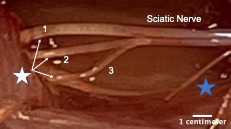
Figure 1. White star shows the three terminal branches of the sciatic nerve. 1) Tibial nerve, 2) common fibular or common peroneal nerve, and 3) sural nerve. The branches were separated by removing a portion of the epineurium using fine forceps. Blue star indicates a small proximal branch of the sciatic nerve that innervates a portion of the hamstring muscle. This image was taken on an AmScope ZM-4TW3-FOR-9M Digital Professional Trinocular Stereo Zoom Microscope at 4.5× zoom.
Materials and reagents
Silastic sheeting (Dow Corning Corporation medical products, catalog number: 501-1)
0.5 mL tubes (Corning, catalog number: 3750)
Thrombin (MP Biomedical, catalog number: 76461-568)
Fibrinogen (Sigma, catalog number: F3879-1G)
Fibrin glue (Akhter et al., 2019; Ward and English, 2019)
Isoflurane (Piramal Healthcare, catalog number: RXISO-250)
Gauze pads (Fisher Brand, catalog number: 22-362-186)
Betadine solution (Purdue Frederick Company, catalog number: 10224)
Ethanol (Thermo Fisher, catalog number: T038181000CS)
10 μL pipette tips (Eppendorf, catalog number: 022492004)
0.9% sodium chloride (NaCl) (Fisher, catalog number: S271-1)
4% PFA (paraformaldehyde prepared in 0.1 M PBS) (Sigma, catalog number: P6148-500G)
1× phosphate buffered saline (PBS) prepared from PBS tablets (Sigma, catalog number: P4417-100TAB)
Euthanasia solution (10 mg/mL made in sterile saline) (Med Vet International, catalog number: RXEUTHASOL)
Sylgard 184 silicone elastomer base and curing agent (Krayden DOW, catalog DC4019862)
Equipment
Cuff electrode
Dumont Forceps #5 (Fine Science Tools, catalog number: 11251-10)
Surgical scissors (Fine Science Tools, catalog number: 14084-09)
Spring scissors (Fine Science Tools, catalog number: 15006-09)
Silastic tubing (Laboratory Tubing, catalog number: 508-006)
Insulated wire (Cooner Wire, catalog number: AS631)
Flexible silicone (Dow Corning, catalog number: Sylgard® 184)
Sewing needle size #9 (Singer, catalog number: 01125)
Table clamp (to hold the silicone tubing in place)
Wooden applicator stick (Electron microscopy sciences, catalog number: 07230)
Silk braided thread size 0 (J.A Daknatel & Son Inc., catalog number: 3-766-900)
Microscope (Nikon, model number: SMZ800)
LED Tester, set at 15 V for checking current leakage from cuff electrode (Hewlett Packard Palo Alto Hp California 630)
For electrical stimulation
Grass Stimulator and Amplifier Box (Ward and English, 2019)
Custom Lab View Program (Ward and English, 2019)
Surgery
Thy-1 YFP-H adult mice (2–4 months old; male and/or female weighing 18–30 g) (Jax laboratory, stock number: 003782)
Surgical drapes (Med-Vet International, catalog number: SKU DR1826)
Needle holder with suture cutter (Fine Science Tools, catalog number: 12502-14)
Hair clipper (Wahl combo kit #9990-1201)
Deltaphase Isothermal Pad (Braintree scientific, model: 39DP)
Warm water circulator (Gaymar TP500)
Surgical stereoscope (AmScope SM-4BZ-80S)
Glass bead sterilizer (Braintree Scientific, catalog number: GER 5287-120V)
Surgical board (Fisher Brand, catalog number: 0900224C)
Surgical tape (3M Micropore tape, 1532-1)
Cotton tipped applicator (Dukal corporation, 9006)
Eye ointment (Refresh P.M.)
Triple antibiotic ointment (Mckesson Medical Surgical Inc, catalog number: 955410)
Meloxicam oral suspension (Med-Vet International, catalog number: RXMELOXIDYL10)
Absorbable: coated Visorb undyed braided polyglycolic acid suture NSF-2 19 mm 3/8 30" (75 cm) (CP medical, catalog number: 421A)
Non-absorbable Monofilament polyamide suture (Redilon 5-0) 1 metric 18" (45 cm) (CP medical, catalog number: 661B)
Software
FIJI (NIH) to process and analyze the images
Microsoft Excel to organize the axon length data
Procedure
Cuff building (Rios et al., 2019)
Take approximately 1 inch of silicon tubing. Insert the tubing onto a wooden applicator that is held by a holder. Under a stereoscope, cut a slit halfway through the tubing (Figures 2 and 3A).
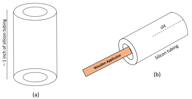
Figure 2. Cuff building schematics. A) Schematic of silicon tubing. B) Silicon tubing is placed on a wooden applicator for ease of handling while building. A 1/2 inch slit is made through the tubing.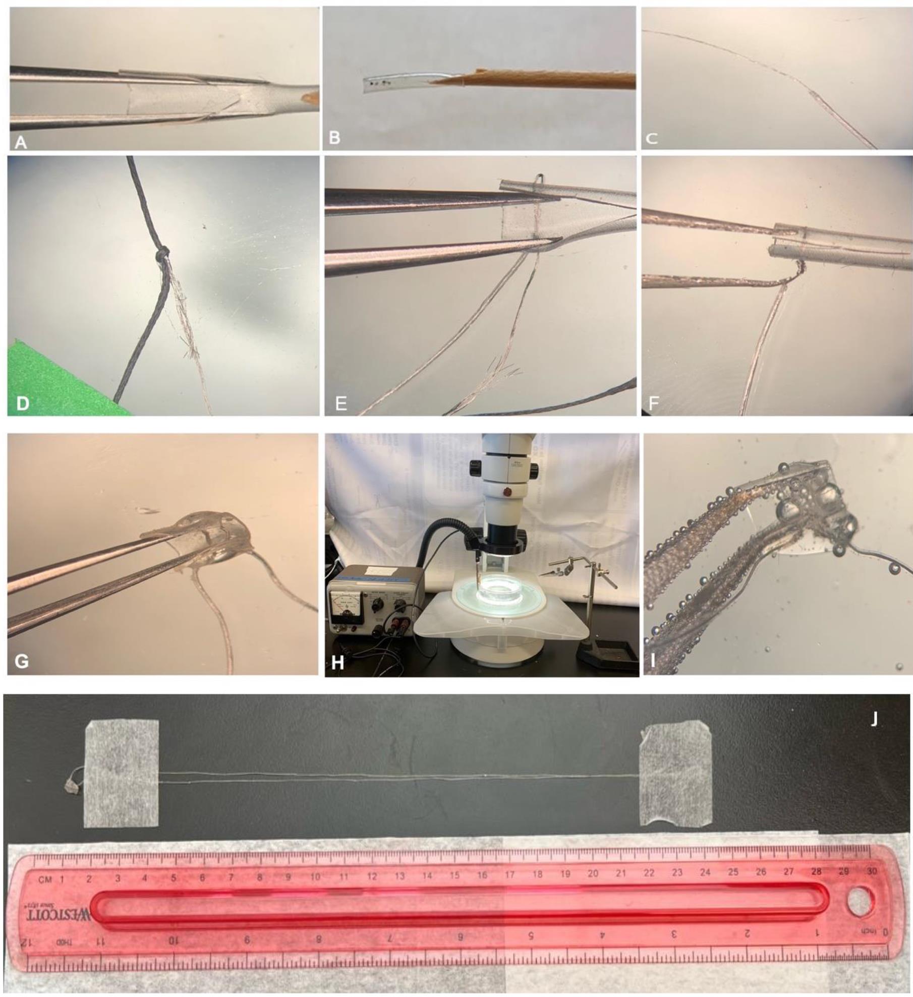
Figure 3. Cuff building procedure. A) Cuff tubing of approximately 1 inch in length. The tube is cut to create a slit. B) A total of six holes are made in the tube: two on the left of the slit and four on the right of the slit. C) Cooner wire is de-insulated approximately 4–5 cm in length. D) The de-insulated wire is tied with a silk thread. E) The silk thread along with the Cooner wire is passed along the first hole through the superior hole, back into the inferior hole, and then back from the first hole. F) The de-insulated wire is wrapped around the insulated wire to secure it, so that the wire does not detach from the cuff tubing. G) Same process (from C–F) is repeated to make a complete cuff consisting of two de-insulated wires lying inside the cuff tubing. The outside exposed wire is covered with flexible silicone to prevent current leakage. The cuff is trimmed to a length of ∼1 cm. H) Setup for testing the cuff (bubble test) consisting of a Petri dish filled with 0.9% NaCl and LED tester maintained at 15 V. I) The cuff shows bubbles escaping only from inside the cuff tubing where the Cooner wire is de-insulated. J) Full view of the custom-made cuff electrode; extra length allows for a more flexible setup on the surgical table (surgical supplies, stimulator, and experimental animal) during electrical stimulation, e.g., a very short cuff requires the stimulus isolation unit to be placed a short distance away from the animal.Using a 30 G needle, make a hole (1) approximately 4–5 mm from the slit on the left side of the tubing. On the right side of the tubing, make a superior hole (2) at 2–3 mm from the slit. Similarly, make an inferior hole (3) at 2–3 mm below the superior hole 2 (Figure 4).
Note: Align hole 1 with 2. Align 3 such that the 1 on the left side of the tubing is in the center of 2 and 3.
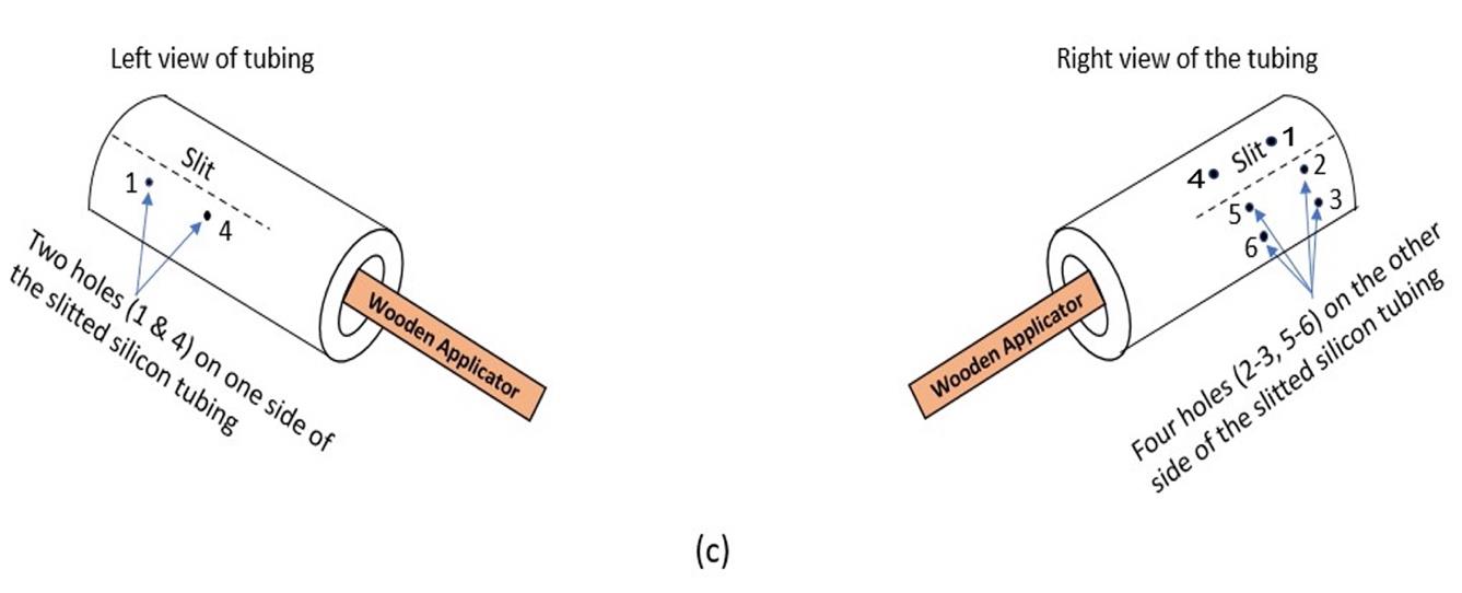
Figure 4. Schematic of the location of holes to be made in the tubing with a 30 G needle. These holes provide passage for the Cooner wire to be threaded through, so that the de-insulated wire rests completely within the tubing.Similarly, make another hole (4) leaving 2–3 cm distance from 1 on the left. On the right view, make a superior hole (5), leaving 2–3 cm distance from 2, and an inferior hole (6) (below 5) leaving 2–3 mm from the superior hole 5. A total of six holes are made in the tubing with the 30 G needle (Figure 4).
Note: Align hole 4 with 5 and 6, such that 4 is in the center of 5 and 6. Holes 4, 5, and 6 are equidistant from 1, 2, and 3.
Take approximately 30 cm of Cooner wire. De-insulate approximately 4–5 cm in length of the tip of the wire (Figures 5 and 3C). Thread 20 cm of silk thread into the eye of a #9 sewing needle. Tie a knot on the de-insulated section of the fine wire with the silk thread. Secure the knot so that it does not detach from the fine wire (Figure 3D).
Note: Cooner wire consists of 13 fine braided metallic wires within insulation. As the insulation is removed at the ends of the wire, the metallic wires tend to fray. Care should be taken to coil it around itself to minimize the fray.
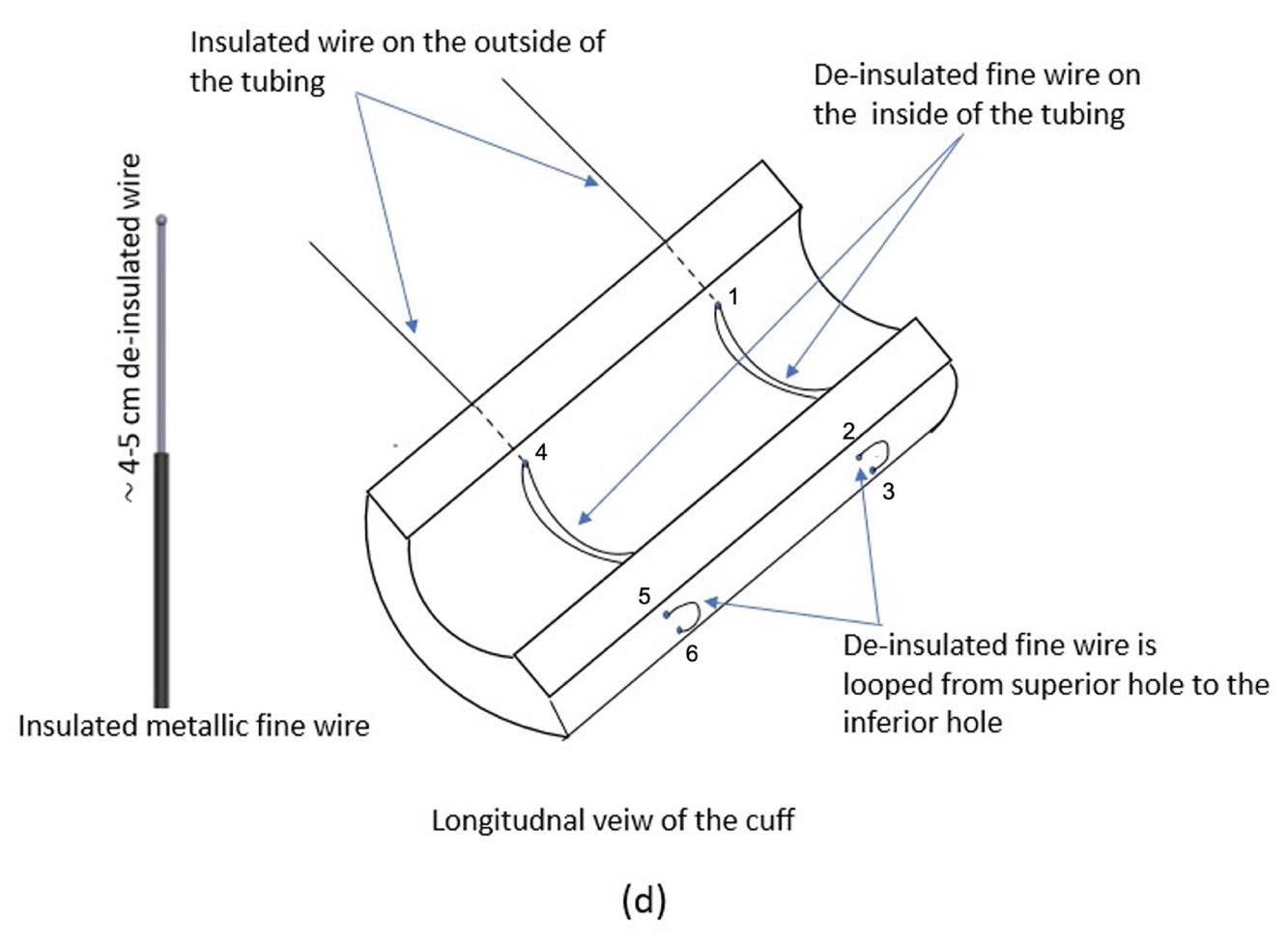
Figure 5. Schematic of the inside of the tubing, showing the placement of insulated and de-insulated portions of the Cooner wirePass the silk thread through hole 1 (left) and then through hole 2 (right), such that a portion of the de-insulated wire lies inside the tubing (Figures 5 and 3E–3F).
Turn the needle 180° and pass it through hole 3 on the right and then out through hole 1 on the left of the tubing again, making sure a portion of the de-insulated wire lies inside the tubing (Figures 5 and 3E–3F). Repeat the process with another 30 cm of Cooner wire, and thread it through hole 4 on the left through to the corresponding two holes 5 and 6 on the right.
The remaining de-insulated wire that comes out of the left hole is tightly coiled 4–5 times around the insulated wire, to secure it from detaching from the cuff (Figure 3F).
Note: Care should be taken to coil the de-insulated wire so that none of the 13 small metallic wires become frayed. Cut off any excess de-insulated wire to minimize current leakage.
Mix 0.8 g of Sylgard 184 silicone elastomer base with 0.1 g of Sylgard 184 silicone elastomer curing agent. Use this mixture to seal any non-insulated metallic fine wire that is outside the cuff tubing to prevent current leakage. The flexible silicon is cured in an incubator maintained at 100 °C for 5 min.
Note: The flexible silicone is repeatedly applied to and cured in the incubator until all the exposed (uninsulated) wire outside the cuff tubing is covered.
Trim the cuff to ∼1 cm in length (Figure 3G). Test the cuff (bubble test) using a LED tester that is maintained at 15 V. Fill a Petri dish with 0.9% NaCl (saline). Submerge the cuff in the saline solution. De-insulate the distal ends (1–2 cm) of the Cooner wire and connect to the LED tester. Perform a bubble test, wherein a properly built cuff should have bubbles escaping only from inside the cuff where the wire is de-insulated. Any bubbles escaping from outside the cuff should be sealed again using the flexible silicone (Figure 3I). This step is critical to prevent off-target stimulation of nearby nerves/muscle.
Surgical preparation
Sterilize all surgical instruments in a glass bead sterilizer maintained at 250 °C for 30 s. Cool the surgical instruments at room temperature for at least 5 min (or until cool to the touch).
Place heating pad or circulator under a surgical board to maintain body heat.
Place the nose cone on the surgical board and secure it with surgical tape.
Thaw out aliquots of thrombin (thrombin is made by adding 25 μL of thrombin stock solution to 975 μL of 45 mM CaCl2) at room temperature. Fibrinogen is prepared by mixing 10 mg of fibrinogen with 100 μL of distilled water until completely dissolved. Fibrinogen tends to coagulate when left at room temperature and should be used within 5–6 h of preparation. Coagulated fibrinogen should not be used because the nerve stumps will not be secured leading to a large gap, which greatly reduces the number of axons able to regenerate.
Weigh the animal and place it in the induction chamber to induce anesthesia (5% isoflurane in 1 L/min oxygen).
Place the animal on the surgical board with its nose fitted to a nose cone. The anesthesia is then maintained at 2% isoflurane. Clip hair using electric hair clipper starting from hip to ankle of the hindlimb.
Remove all the hair and the first drape from under the animal. Wipe the hindlimb of the animal with alcohol and betadine in succession for three times each.
Perform a toe pinch to check any reaction to ensure the animal is within the surgical plane. Titrate isoflurane as needed.
Nerve surgery should be performed with aide of surgical microscope.
Drape the animal with sterile drape such that only the site of surgery is exposed.
Identify the femur by palpating the skin.
Make a 4 cm incision along the length of the femur. Blunt dissect the fascia between the biceps femoris and hamstring muscles.
Using #5 forceps, carefully isolate the sciatic nerve from the underlying connective tissues (Figure 6A).
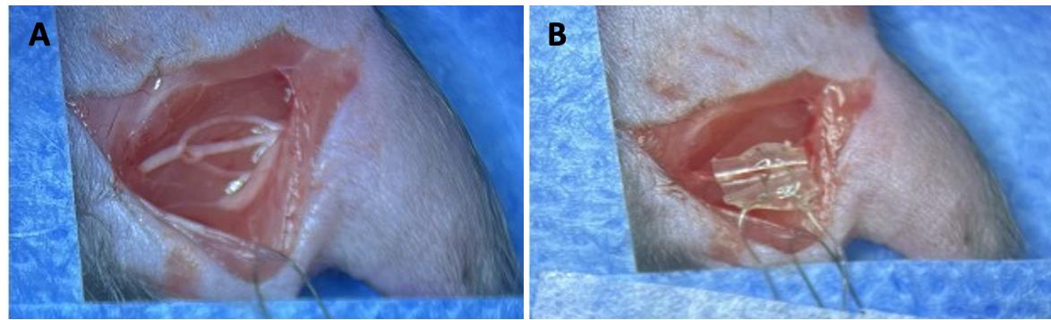
Figure 6. Sciatic nerve stimulation with cuff. A) Sciatic nerve is exposed by making a ~4 cm incision on the skin. B) A custom-made cuff is wrapped around the whole sciatic nerve (or a chosen branch), such that the nerve rests on top of the de-insulated wire inside the cuff. The de-insulated distal ends of the cuff are connected to a grass stimulator. Nerve stimulation can occur prior to or after nerve transection and repair, which has been previously detailed (Akhter et al., 2019).Wrap the cuff around the sciatic nerve such that the nerve is in contact with the de-insulated wire inside the cuff (Figure 6B). Connect the de-insulated wires at the distal tip of the cuff to the amplifier box. Using a grass stimulator, stimulate the nerve for 1 h at 20 Hz (Gordon 2020). Stimulating the nerve immediately prior to transection allows for visual confirmation of stimulation (visible muscle twitches).
After stimulating the nerve for 1 h, place a small 4 mm square of silastic sheeting under the nerve. Apply fibrin glue consisting of thrombin (2 μL) and fibrinogen (1 μL) (2:1 ratio) to the sciatic nerve, so that the nerve is secured to the silastic sheet (1–2 min for the fibrin glue to coagulate).
Then, completely transect the nerve with sharp micro scissors. Care should be taken so that the cut nerve stumps are in close proximity of each other. Apply fibrin glue again for 1–2 min.
Without disturbing the transected nerve, suture the muscles using absorbable suture and the skin using non-absorbable nylon suture.
Apply triple antibiotic cream on the surgical site using a sterile cotton-tipped applicator.
Post-surgery
Remove the animal from the nose cone and place it into a clean recovery cage (without bedding) placed on a warm water circulating heating pad (Gaymar TP500). Once the animal is ambulatory, administer oral analgesic [meloxicam (5 mg/kg)]. Two weeks after nerve transection, there should be no observable scar formation in the skin or muscle.
Two weeks after nerve transection, inject the animal with 0.3–0.4 mL of euthanasia solution (10 mg/mL). Following euthanasia, dissect the sciatic nerve from the animal (4 mm proximal to the repair site to the distal end). Care should be taken to carefully collect the whole length of the distal nerve without damaging the repair site.
Fix the nerve in 1 mL of 4% PFA for 1 h at room temperature and then transfer to 1× PBS for 5–10 min.
Place the nerve on a clean slide and add a few drops of Vectashield with DAPI (hard mount) to the nerve.
Place a glass coverslip on the nerve. Add weights (3–5 g) on top of the coverslip so as to flatten the nerve for 24 h.
Image the nerve using Nikon AR125 HD confocal microscope using GFP (488) laser with a 10× objective.
Use the image tile function so that the whole length of the nerve on the slide is visible on the computer screen. Set up Z stack with a step size of 4.75 microns. Apply a line average of 4 to reduce background noise. Image the nerve on resonant mode for faster imaging. Do not apply zoom for imaging. The image is automatically stitched by the Nikon software to reconstruct the proximal and distal end of the nerve in three dimensions.
Data analysis
Load the nerve image into FIJI software (NIH).
Using the straight-line tool with a diameter of 10 mm, place a region of interest (ROI) at the injury site. When the image is zoomed in, the injury site is apparent by the disrupted and unorganized axons. That point is where the transection of the nerve was performed: the injury site.
Using the freehand tool, measure the length of each axon from the repair site to the distal tip following the axon throughout the Z stack. When measuring the length of each axon, always start measuring the shortest axons first, as they will be difficult to visualize later when longer axon profiles are overlaid on the image (Figure 7). Compare the length of axon growth between electrically stimulated nerves and untreated nerves. Ensure the scale bar and image calibration is correct (J > Tools > Scale bar).
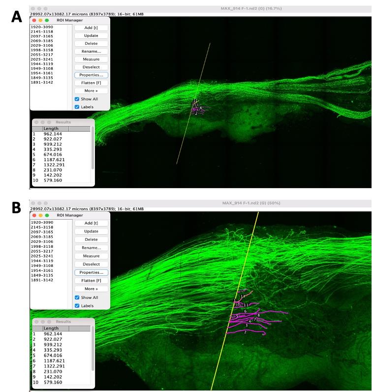
Figure 7. Image of a nerve from a Thy-1-YFP-H mouse. The regenerating axons can be visualized by the YFP reporter. A) Beginning with the shortest regenerating axons, individual axon profile lengths are measured by tracing through the Z stack. B) Zoomed image of the nerve showing the length of growing axons from the injury site.Sort the length of each regenerating axons into bins of increasing lengths in Microsoft Excel.
Calculate the frequency by selecting the entire column of frequency and then use the formula {= frequency (values in the length column, all values in the bin column)}.
Calculate the proportion using the formula = [(each frequency value × 100)/total number of axons].
Then, calculate the cumulative percentage of total number of regenerating axons.
Electrically stimulated nerves exhibit longer axons compared to non-stimulated nerves, i.e., Untreated (Figure 8).
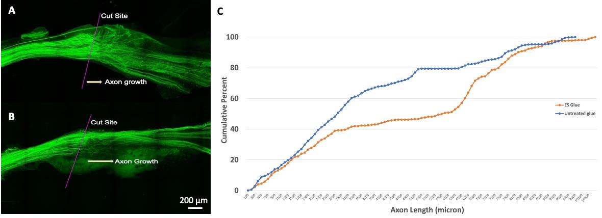
Figure 8. Stimulated vs. unstimulated nerve growth following nerve transection. A) Image of a nerve following transection and repair with fibrin glue. The injury site and direction of axon growth are indicated. Note that many regenerating axon profiles are close to the repair site. B) Image of a nerve following electrical stimulation and transection and repair with fibrin glue. The injury site and direction of axon growth are indicated. Note the longer length of many regenerating axons compared to the untreated nerve. C) The cumulative frequency distributions of each group. The cumulative distribution of axon lengths in the electrically stimulated fibrin glue–repaired group is significantly shifted to the right, which indicates longer axons.
Notes
As with all experimental models, this has its own advantages and disadvantages. In this protocol, we utilized a reporter mouse (Thy-1-YFP-H). The reporter is advantageous in that nerves do not require sectioning and immunostaining. Alternatively, peripheral regeneration assays can use nerves from wildtype mice C57BL/6J (Jackson laboratory, stock no. 000664) by sectioning and immunostaining the nerves with neurofilament heavy chain (NF200) (Dun and Parkinson, 2015). SCG10 is another commonly used antibody, but it is preferentially expressed in regenerating sensory and sympathetic axons rather than motor (Shin et al., 2014; Lee et al., 2022). Because of their abundance, precise analysis of individual axons is difficult when using NF200 or SCG10.
Care should be taken not to add excess flexible silicon on the cuff to cover the de-insulated wires outside the cuff, because it makes the cuff bigger and bulkier. Bulkier cuffs are more difficult to apply to the nerve and also require a larger surgical site. Furthermore, if the cuff is too bulky, the nerve might lose contact with the de-insulated wire inside the cuff.
When properly cared for, cuffs can be re-used for multiple stimulations. The cuff is cleaned with soap and water and wiped gently with a delicate task wipe soaked in 70% ethanol. Eventually, the cuff will become leaky. It is good practice to bubble test each cuff before use. If the bubble test shows the bubbles escaping from inside and outside of the cuff, then a new cuff must be built.
Fibrinogen tends to coagulate; hence, it should always be made fresh on the day of the surgery. When doing multiple surgeries, fresh pipette tips are used to extract the solution each time to avoid mixing with thrombin, which will cause it to coagulate.
To avoid mushrooming of the cut nerve stumps, sharp spring scissors should be used to transect the nerve.
In our studies, we routinely use fibrin glue to repair transected nerves and found that fibrin glue is an adjuvant to activity-based therapy, such as exercise (Wariyar et al., 2022). If fibrin glue is not used, another means of securing the cut nerve stumps together must be used (fine sutures).
English and colleagues reported a sex difference in axon regeneration when using a form of activity-based treatment (treadmill running) (Wood et al., 2012). At the transcriptional level, sexually dimorphic programs are acutely activated by nerve injury (Chernov and Shubayev, 2022), which may influence regenerative ability and response to treatments. Potential sex differences must be considered in experimental design.
Ethical considerations
All procedures involving animals were performed according to and approved by the Institutional Animal Care and Use Committee of Emory University.
Acknowledgments
This work was supported in part by the NIH National Institute of Neurological Disorders and Stroke under award number K01NS124912 as well as a developmental grant from the NIH-funded Emory Specialized Center of Research Excellence in Sex Differences U54AG062334.
Competing interests
The authors declare that no competing interests exist.
References
- Akhter, E., Rotterman, T., English, A. and Alvarez, F. (2019). Sciatic Nerve Cut and Repair Using Fibrin Glue in Adult Mice. Bio Protoc 9(18): e3363.
- Al-Majed, A. A., Neumann, C. M., Brushart, T. M. and Gordon, T. (2000). Brief Electrical Stimulation Promotes the Speed and Accuracy of Motor Axonal Regeneration. J. Neurosci. 20(7): 2602–2608.
- Barber, B., Seikaly, H., Ming Chan, K., Beaudry, R., Rychlik, S., Olson, J., Curran, M., Dziegielewski, P., Biron, V., Harris, J., et al. (2018). Intraoperative Brief Electrical Stimulation of the Spinal Accessory Nerve (BEST SPIN) for prevention of shoulder dysfunction after oncologic neck dissection: a double-blinded, randomized controlled trial. J. Otolaryngol. Head Neck Surg. 47(1): e1186/s40463-017-0244-9.
- Brushart, T. M., Hoffman, P. N., Royall, R. M., Murinson, B. B., Witzel, C. and Gordon, T. (2002). Electrical Stimulation Promotes Motoneuron Regeneration without Increasing Its Speed or Conditioning the Neuron. J. Neurosci. 22(15): 6631–6638.
- Brushart, T. M., Jari, R., Verge, V., Rohde, C. and Gordon, T. (2005). Electrical stimulation restores the specificity of sensory axon regeneration. Exp. Neurol. 194(1): 221–229.
- Bulut, T., Tahta, M., Sener, U. and Sener, M. (2018). Inter- and intra-tester reliability of sensibility testing in healthy individuals. J. Plast. Surg. Hand Surg. 52(3): 189–192.
- Chernov, A. V. and Shubayev, V. I. (2022). Sexually dimorphic transcriptional programs of early-phase response in regenerating peripheral nerves. Front. Mol. Neurosci. 15: e958568.
- Dun, X. p. and Parkinson, D. B. (2015). Visualizing Peripheral Nerve Regeneration by Whole Mount Staining. PLoS One 10(3): e0119168.
- Elzinga, K., Tyreman, N., Ladak, A., Savaryn, B., Olson, J. and Gordon, T. (2015). Brief electrical stimulation improves nerve regeneration after delayed repair in Sprague Dawley rats. Exp. Neurol. 269: 142–153.
- Enax-Krumova, E. K., Pohl, S., Westermann, A. and Maier, C. (2017). Ipsilateral and contralateral sensory changes in healthy subjects after experimentally induced concomitant sensitization and hypoesthesia. BMC Neurol. 17(1): e1186/s12883-017-0839-9.
- English, A. W., Schwartz, G., Meador, W., Sabatier, M. J. and Mulligan, A. (2007). Electrical stimulation promotes peripheral axon regeneration by enhanced neuronal neurotrophin signaling. Dev. Neurobiol. 67(2): 158–172.
- Geremia, N. M., Gordon, T., Brushart, T. M., Al-Majed, A. A. and Verge, V. M. (2007). Electrical stimulation promotes sensory neuron regeneration and growth-associated gene expression. Exp. Neurol. 205(2): 347–359.
- Gordon, T. (2020). Peripheral Nerve Regeneration and Muscle Reinnervation. Int. J. Mol. Sci. 21(22): 8652.
- Gordon, T. and English, A. W. (2016). Strategies to promote peripheral nerve regeneration: electrical stimulation and/or exercise. Eur. J. Neurosci. 43(3): 336–350.
- Gordon, T., Amirjani, N., Edwards, D. C. and Chan, K. M. (2010). Brief post-surgical electrical stimulation accelerates axon regeneration and muscle reinnervation without affecting the functional measures in carpal tunnel syndrome patients. Exp. Neurol. 223(1): 192–202.
- Höke, A. and Brushart, T. (2010). Introduction to special issue: Challenges and opportunities for regeneration in the peripheral nervous system. Exp. Neurol. 223(1): 1–4.
- Lee, N., Kim, S. and Lee, J. (2022). Impairment of peripheral nerve regeneration by insufficient activation of the HGF/c-Met/c-Jun pathway in aged mice. Heliyon 8(11): e11411.
- Lee, S. K. and Wolfe, S. W. (2000). Peripheral Nerve Injury and Repair. J. Am. Acad. Orthop. Surg. 8(4): 243–252.
- Rios, M., Bucksot, J., Rahebi, K., Engineer, C., Kilgard, M. and Hays, S. (2019). Protocol for Construction of Rat Nerve Stimulation Cuff Electrodes. Methods Protoc. 2(1): 19.
- Senger, J. L., Chan, A. W. M., Chan, K. M., Kwan-Wong, T., Acton, L., Olson, J. and Webber, C. A. (2020a). Conditioning Electrical Stimulation Is Superior to Postoperative Electrical Stimulation in Enhanced Regeneration and Functional Recovery Following Nerve Graft Repair. Neurorehabil. Neural Repair 34(4): 299–308.
- Senger, J. L., Chan, K. M. and Webber, C. A. (2020b). Conditioning electrical stimulation is superior to postoperative electrical stimulation, resulting in enhanced nerve regeneration and functional recovery. Exp. Neurol. 325: 113147.
- Senger, J. L., Chan, K. M., Macandili, H., Chan, A. W., Verge, V. M., Jones, K. E. and Webber, C. A. (2019). Conditioning electrical stimulation promotes functional nerve regeneration. Exp. Neurol. 315: 60–71.
- Senger, J., Verge, V., Macandili, H., Olson, J., Chan, K. and Webber, C. (2018). Electrical stimulation as a conditioning strategy for promoting and accelerating peripheral nerve regeneration. Exp. Neurol. 302: 75–84.
- Shapira, Y., Sammons, V., Forden, J., Guo, G. F., Kipp, A., Girgulis, J., Mishra, T., de Villers Alant, J. D. and Midha, R. (2019). Brief Electrical Stimulation Promotes Nerve Regeneration Following Experimental In-Continuity Nerve Injury. Neurosurgery 85(1): 156–163.
- Shin, J. E., Geisler, S. and DiAntonio, A. (2014). Dynamic regulation of SCG10 in regenerating axons after injury. Exp. Neurol. 252: 1–11.
- Sulaiman, O. A. and Gordon, T. (2000). Effects of short- and long-term Schwann cell denervation on peripheral nerve regeneration, myelination, and size. Glia 32(3): 234–246.
- Sulaiman, W. A. R. and Kline, D. G. (2006). Nerve surgery: a review and insights about its future. Clin. Neurosurg. 53: 38–47.
- Sulaiman, W. A., Midha, R. and Gordon, T. (2011). Pathophysiology of Surgical Nerve Disorders. Youmans Neurological Surgery: 2368–2379.
- Sulaiman, W. and Gordon, T. (2013). Neurobiology of peripheral nerve injury, regeneration, and functional recovery: from bench top research to bedside application. Ochsner J. 13(1): 100–108.
- Thompson, N. J., Sengelaub, D. R. and English, A. W. (2014). Enhancement of peripheral nerve regeneration due to treadmill training and electrical stimulation is dependent on androgen receptor signaling. Dev. Neurobiol. 74(5): 531–540.
- Wang, M. L., Rivlin, M., Graham, J. G. and Beredjiklian, P. K. (2019). Peripheral nerve injury, scarring, and recovery. Connect. Tissue Res. 60(1): 3–9.
- Ward, P. J. and English, A. (2019). Optical Stimulation and Electrophysiological Analysis of Regenerating Peripheral Axons. Bio Protoc 9(12): e3281.
- Wariyar, S. S., Brown, A. D., Tian, T., Pottorf, T. S. and Ward, P. J. (2022). Angiogenesis is critical for the exercise-mediated enhancement of axon regeneration following peripheral nerve injury. Exp. Neurol. 353: 114029.
- Wong, J. N., Olson, J. L., Morhart, M. J. and Chan, K. M. (2015). Electrical stimulation enhances sensory recovery: A randomized controlled trial. Ann. Neurol. 77(6): 996–1006.
- Wood, K., Wilhelm, J. C., Sabatier, M. J., Liu, K., Gu, J. and English, A. W. (2012). Sex differences in the effectiveness of treadmill training in enhancing axon regeneration in injured peripheral nerves. Dev. Neurobiol. 72(5): 688–698.
- Zheng, M. X., Hua, X. Y., Feng, J. T., Li, T., Lu, Y. C., Shen, Y. D., Cao, X. H., Zhao, N. Q., Lyu, J. Y., Xu, J. G., et al. (2018). Trial of Contralateral Seventh Cervical Nerve Transfer for Spastic Arm Paralysis. N. Engl. J. Med. 378(1): 22–34.
Article Information
Publication history
Published: Oct 5, 2023
Copyright
© 2023 The Author(s); This is an open access article under the CC BY-NC license (https://creativecommons.org/licenses/by-nc/4.0/).
How to cite
Wariyar, S. S. and Ward, P. J. (2023). Application of Electrical Stimulation to Enhance Axon Regeneration Following Peripheral Nerve Injury. Bio-protocol 13(19): e4833. DOI: 10.21769/BioProtoc.4833.
Category
Neuroscience > Peripheral nervous system > Sciatic nerve
Neuroscience > Neuroanatomy and circuitry > Sciatic nerve
Do you have any questions about this protocol?
Post your question to gather feedback from the community. We will also invite the authors of this article to respond.
![]() Tips for asking effective questions
Tips for asking effective questions
+ Description
Write a detailed description. Include all information that will help others answer your question including experimental processes, conditions, and relevant images.